AUTOMATIC TRANSAXLE ASSEMBLY REMOVAL
-
DISCHARGE FUEL SYSTEM PRESSURE
Tech Tips
-
RECOVER REFRIGERANT FROM REFRIGERATION SYSTEM
-
Start the engine.
-
Turn the A/C switch on.
-
Operate the cooler compressor at an engine speed of approximately 1000 rpm for 5 to 6 minutes to circulate the refrigerant. This causes most of the compressor oil from the various components of the A/C system to collect in the A/C compressor.
-
Stop the engine.
-
Recover the refrigerant from the A/C system using a refrigerant recovery unit.
-
-
REMOVE COOL AIR INTAKE DUCT SEAL
-
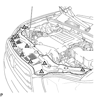
Remove the 11 clips and cool air intake duct seal.
-
-
DISCONNECT CABLE FROM NEGATIVE BATTERY TERMINAL
CAUTION:
Wait at least 90 seconds after disconnecting the cable from the negative (-) battery terminal to prevent airbag and seat belt pretensioner activation.
Note
When disconnecting the cable, some systems need to be initialized after the cable is reconnected Click here.
-
REMOVE BATTERY
-
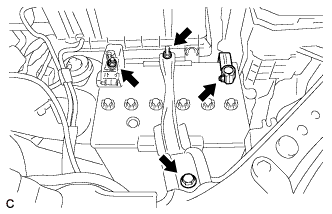
Loosen the nut, and disconnect the negative battery terminal.
CAUTION:
Wait for 90 seconds after disconnecting the cable to prevent the airbag working.
Note
When disconnecting the cable, some systems need to be initialized after the cable is reconnected Click here.
-
Remove the nut, and separate the positive battery terminal cable.
-
Loosen the nut, and remove the bolt and battery clamp.
-
Remove the battery and battery tray.
-
-
PLACE FRONT WHEELS FACING STRAIGHT AHEAD
-
REMOVE FRONT WHEELS
-
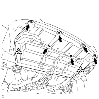
REMOVE ENGINE UNDER COVER ASSEMBLY
-

Remove the 2 bolts and engine under cover assembly RR.
-

Remove the 2 bolts, 2 screws, 5 clips and engine under cover assembly.
-
-
REMOVE NO. 1 ENGINE UNDER COVER
-
Remove the 6 bolts, 2 clips and No. 1 engine under cover.
-
-
REMOVE NO. 2 ENGINE UNDER COVER
-
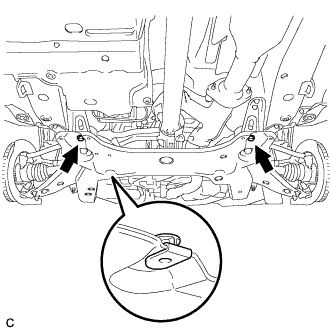
Remove the 2 bolts and No. 2 engine under cover.
-
-
REMOVE FLOOR UNDER COVER LH
-
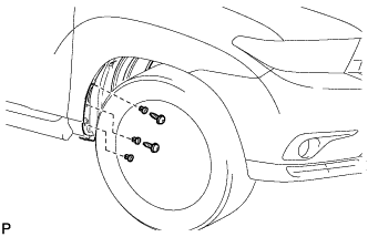
REMOVE FRONT FENDER MOULDING SUB-ASSEMBLY LH
-
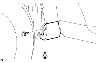
Remove the clip.
-
Using a 4 mm hexagon wrench, remove the screw.
-
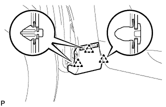
Peel off the double-sided tape and disengage the 3 clips, and then remove the front fender moulding sub-assembly.
-
Remove the pad from the front fender moulding sub-assembly.
-
Remove the 2 No. 4 clips from the front fender moulding sub-assembly.
-
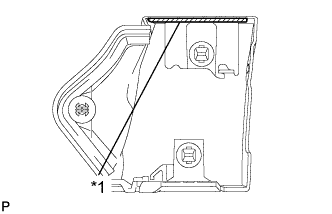
Text in Illustration *1 Double-sided Tape Remove the double-sided tape from the front fender moulding sub-assembly.
-
-
REMOVE FRONT FENDER MOULDING SUB-ASSEMBLY RH
Tech Tips
Use the same procedure as for the LH side.
-
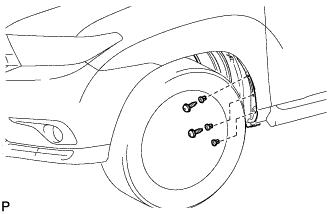
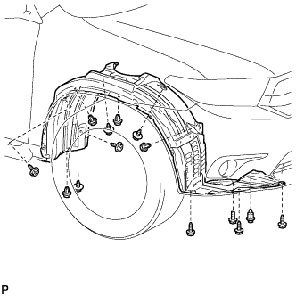
REMOVE FRONT FENDER LINER LH
-
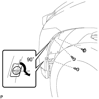
Remove the screw.
-
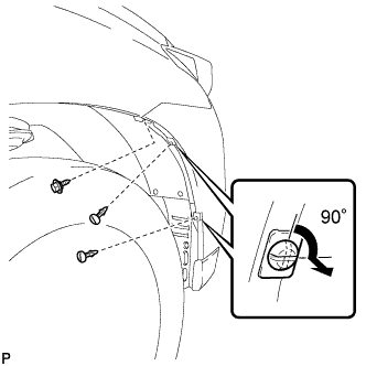
Using a screwdriver, turn the pin 90 degrees and remove the 2 pin hold clips.
-
Using a 4 mm hexagon wrench, remove the 2 screws.
-
Remove the 3 grommets.
Tech Tips
The grommets need to be replaced with new ones because they will break when they are removed.
-
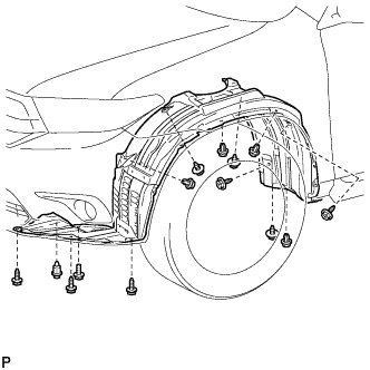
Remove the 5 clips.
-
Remove the bolt, 8 screws and front fender liner LH.
-
-
REMOVE FRONT FENDER LINER RH
-
Remove the screw.
-
Using a screwdriver, turn the pin 90 degrees and remove the 2 pin hold clips.
-
Using a 4 mm hexagon wrench, remove the 2 screws.
-
Remove the 3 grommets.
Tech Tips
The grommets need to be replaced with new ones because they will break when they are removed.
-
Remove the 5 clips
-
Remove the bolt, 8 screws and front fender liner RH.
-
-
REMOVE FRONT FENDER APRON SEAL LH
-
Remove the 2 bolts, clip and front fender apron seal LH.
-
-
REMOVE FRONT FENDER APRON SEAL RH
-
Remove the 2 bolts, clip and front fender apron seal RH.
-
-
DRAIN ENGINE OIL
-
DRAIN ENGINE COOLANT
Note
Do not remove the radiator cap sub-assembly, cylinder block drain cock plugs or radiator drain cock plug while the engine and radiator assembly are still hot. Pressurized, hot engine coolant and steam may be released and cause serious burns.
-
Loosen the radiator drain cock plug.
-
Loosen the cylinder block drain cock plug. (for Bank 1)
-
Loosen the cylinder block drain cock plug. (for Bank 2, w/ Cylinder Block Drain Cock Plug)
-
Remove the radiator cap sub-assembly.
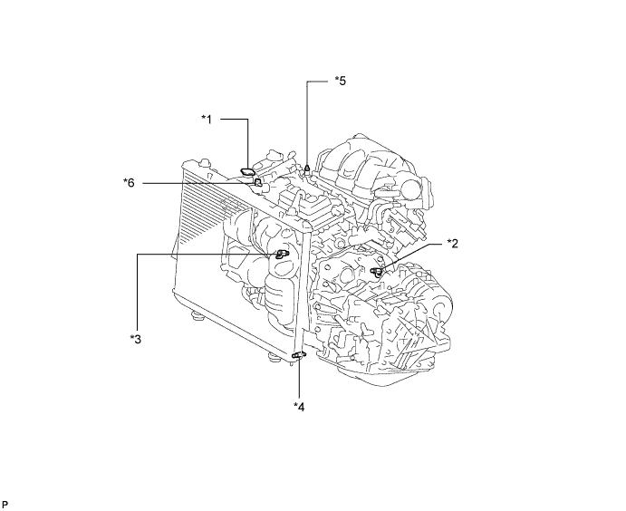
Text in Illustration *1 Radiator Cap Sub-assembly *2 Cylinder Block Drain Cock Plug (for Bank 1) *3 Cylinder Block Drain Cock Plug (for Bank 2, w/ Cylinder Block Drain Cock Plug) *4 Radiator Drain Cock Plug *5 Air Drain Cock Plug *6 Air Drain Plug Tech Tips
Collect the engine coolant in a container and dispose of it according to the regulations in your area.
-
-
DRAIN AUTOMATIC TRANSAXLE FLUID
-
Remove the drain plug and gasket, and drain ATF.
-
Install a new gasket and the drain plug.
- Torque:
- 49 N*m { 500 kgf*cm, 36 ft.*lbf }
-
-
REMOVE FRONT WIPER ARM AND BLADE ASSEMBLY LH
-
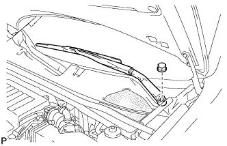
Remove the nut, and the front wiper arm and blade assembly LH.
-
-
REMOVE FRONT WIPER ARM AND BLADE ASSEMBLY RH
-
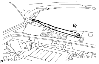
Remove the nut, and the front wiper arm and blade assembly RH.
-
-
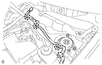
REMOVE COWL TOP VENTILATOR LOUVER SUB-ASSEMBLY
-
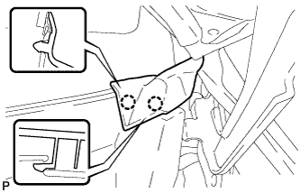
Disengage the 2 claws and disconnect the front fender to cowl side seal LH.
-
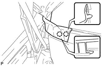
Disengage the 2 claws and disconnect the front fender to cowl side seal RH.
-
Remove the 2 clips.
-
Disengage the 20 claws and remove the cowl top ventilator louver sub-assembly.
-
-
REMOVE WINDSHIELD WIPER MOTOR AND LINK ASSEMBLY
-
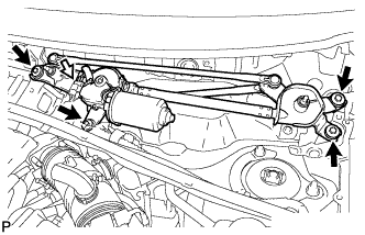
Disconnect the connector.
-
Remove the 4 bolts, and the windshield wiper motor and link assembly.
-
-
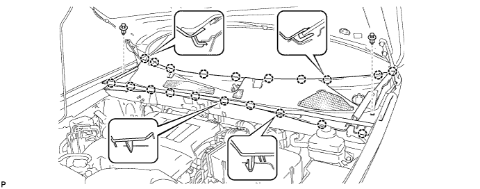
REMOVE OUTER COWL TOP PANEL SUB-ASSEMBLY (for LHD)
-
Remove the 4 clips, and separate the engine wire.
-
Remove the 8 bolts, 6 nuts and front outer cowl top panel sub-assembly.
-
-
REMOVE OUTER COWL TOP PANEL SUB-ASSEMBLY (for RHD)
-
Remove the 4 clips, and separate the engine wire.
-
Remove the 8 bolts, 6 nuts and front outer cowl top panel sub-assembly.
-
-
REMOVE V-BANK COVER SUB-ASSEMBLY
-
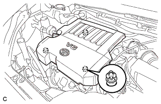
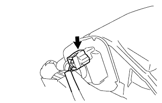
Hold the front of the V-bank cover sub-assembly and raise it to disengage the 2 clips on the front of the V-bank cover sub-assembly. Continue rising the V-bank cover sub-assembly to disengage the clip on the rear of the V-bank cover sub-assembly and remove the V-bank cover sub-assembly.
Note
Attempting to disengage both front and rear clips at the same time may cause the V-bank cover sub-assembly to break.
-
-
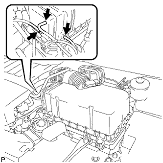
REMOVE NO. 2 AIR CLEANER INLET
-
Disconnect the 2 vacuum switching valve clamps.
-
Disconnect the 2 vacuum hoses.
-
Remove the 2 bolts and No. 2 air cleaner inlet.
-
-
REMOVE NO. 1 AIR CLEANER INLET
-
Disconnect the 2 vacuum hoses, and remove the 2 bolts and No. 1 air cleaner inlet.
-
-
REMOVE AIR CLEANER CAP SUB-ASSEMBLY
-
Disconnect the 3 vacuum hoses.
-
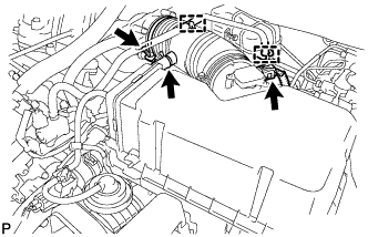
Loosen the No. 1 air cleaner hose clamp.
-
Disconnect the hose clamps and No. 2 ventilation hose.
-
Disconnect the mass air flow meter connector.
-
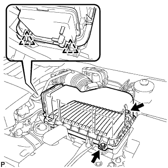
Release the 2 clips, and remove the 2 bolts.
-
Remove the air cleaner cap sub-assembly and air cleaner filter element.
-
-
REMOVE AIR CLEANER FILTER ELEMENT SUB-ASSEMBLY
-
Remove the air cleaner filter element sub-assembly.
-
-
REMOVE AIR CLEANER CASE SUB-ASSEMBLY
-
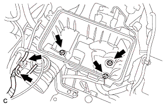
Remove the 3 bolts, disconnect the hose and the connector, and remove the air cleaner case sub-assembly.
-
-
REMOVE AIR CLEANER BRACKET
-
Remove the 2 bolts and air cleaner bracket.
-
-
SEPARATE BRAKE MASTER CYLINDER RESERVOIR ASSEMBLY (for LHD)
-
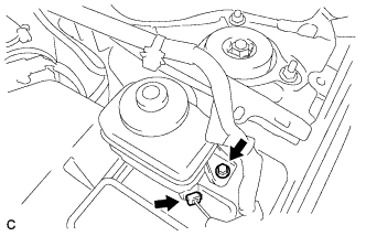
Disconnect the level warning switch connector.
-
Remove the bolt, and separate the brake master cylinder reservoir assembly.
-
-
REMOVE RESERVOIR BRACKET (for LHD)
-
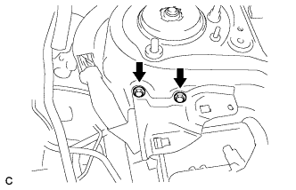
Remove the 2 bolts and reservoir bracket.
-
-
SEPARATE BRAKE MASTER CYLINDER RESERVOIR ASSEMBLY (for RHD)
-
Disconnect the level warning switch connector.
-
Remove the bolt, and separate the brake master cylinder reservoir assembly.
-
-
REMOVE RESERVOIR BRACKET (for RHD)
-
Remove the 2 bolts and reservoir bracket.
-
-
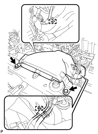
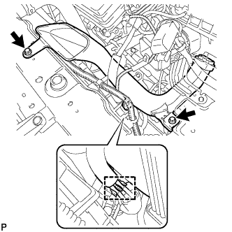
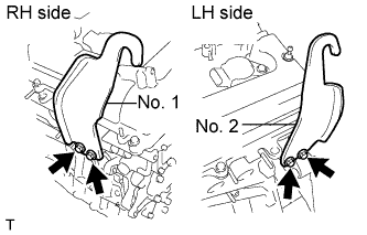
REMOVE NO. 2 ENGINE MOUNTING STAY RH
-
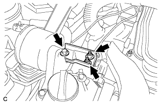
Remove the bolt, 2 nuts and No. 2 engine mounting stay RH.
-
-
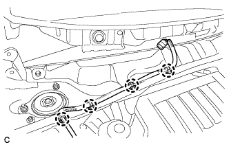
REMOVE ENGINE MOVING CONTROL ROD
-
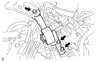
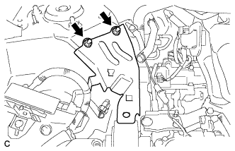
Remove the 3 bolts and engine moving control rod.
-
-
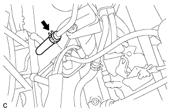
DISCONNECT NO. 1 FUEL VAPOR FEED HOSE
-
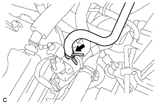
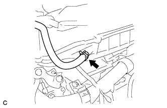
Slide the clamp and disconnect the No. 1 fuel vapor feed hose.
-
-
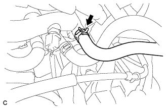
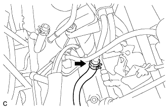
DISCONNECT NO. 1 RADIATOR HOSE
-
Disconnect the clamp.
-
Using pliers, grip the claws of the clip and slide the clip to disconnect the No. 1 radiator hose from the water outlet.
-
-
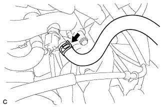
DISCONNECT NO. 2 RADIATOR HOSE
-
Using pliers, grip the claws of the clip and slide the clip to disconnect the No. 2 radiator hose from the water inlet.
-
-
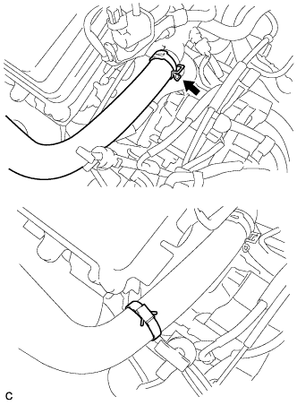
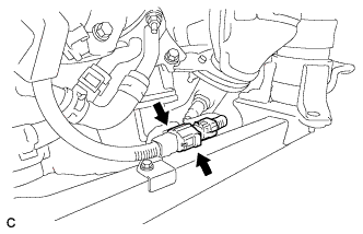
DISCONNECT HEATER WATER HOSE OUTLET B
-
Using pliers, grip the claws of the clip and slide the clip to disconnect heater water outlet hose B from the water inlet.
-
-
DISCONNECT HEATER WATER HOSE INLET B
-
Using pliers, grip the claws of the clip and slide the clip to disconnect heater water inlet hose B from the water outlet.
-
-
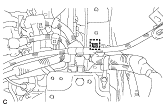
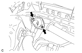
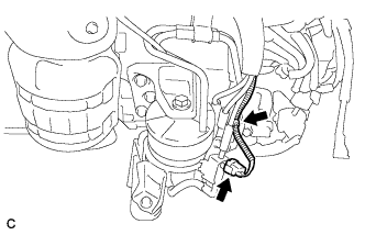
DISCONNECT FUEL TUBE SUB-ASSEMBLY
-
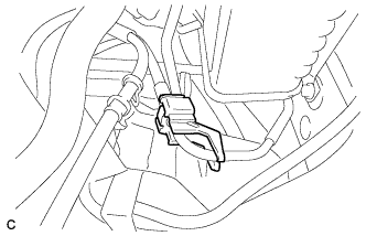
Remove the No. 1 fuel pipe clamp.
-
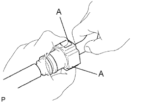
Disconnect the fuel tube from the fuel pipe pinching part A with your fingers as shown in the illustration.
Note
-
Check for dirt and foreign objects on the pipe and around the connector. Clean if necessary and then disconnect the connector.
-
Disconnect the connector by hand.
-
Do not bend, fold or rotate the nylon tube.
-
If the pipe and connector are stuck together, push and pull the connector until it becomes free.
-
Put the pipe and connector ends in plastic bags to prevent damage and contamination.
-
-
-
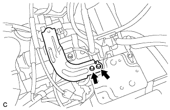
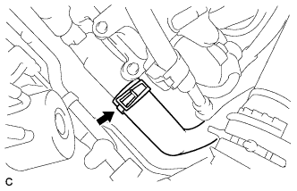
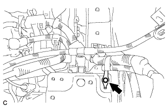
DISCONNECT OIL COOLER INLET HOSE
-
Using pliers, grip the claws of the clip and slide the clip to disconnect the No. 2 transmission oil cooler hose.
-
-
REMOVE OIL COOLER OUTLET HOSE
-
Using pliers, grip the claws of the clip and slide the clip to disconnect the oil cooler outlet hose.
-
-
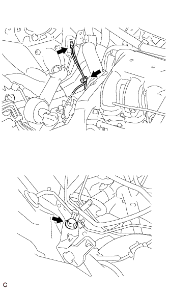
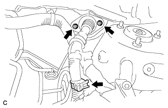
DISCONNECT TRANSMISSION CONTROL CABLE ASSEMBLY
-
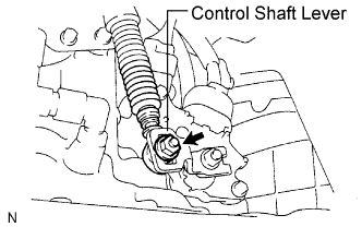
Remove the nut from the control shaft lever.
-
Disconnect the transmission control cable assembly from the control shaft lever.
-
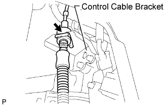
Remove the clip and disconnect the transmission control cable assembly from the control cable bracket.
-
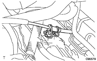
Disconnect the transmission control cable assembly from the control cable clamp.
-
-
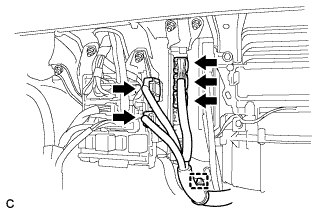
DISCONNECT ENGINE WIRE (for LHD)
-
Disconnect the engine wire from the engine room relay block.
-
Remove the No. 1 relay block cover.
-
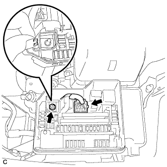
Remove the nut.
-
Disconnect the engine wire connector from the engine room relay block.
-
Unlock the engine wire. Pull the engine room wire.
-
-
Disconnect the engine wire clamp.
-
Remove the bolt, and separate the ground cables.
-
Disconnect the heated oxygen sensor connector and clamp.
-
Remove the 2 bolts and 2 ground cables.
-
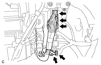
Disconnect the 3 ECM connectors, 2 junction block connectors and clamp.
-
Remove the 2 nuts and clamp, and separate the engine wire from the body.
-
-
DISCONNECT ENGINE WIRE (for RHD)
-
Disconnect the engine wire from the engine room relay block.
-
Remove the No. 1 relay block cover.
-
Remove the nut.
-
Disconnect the engine wire connector from the engine room relay block.
-
Unlock the engine wire. Pull the engine room wire.
-
-
Disconnect the engine wire clamp.
-
Remove the bolt, and separate the ground cables.
-
Disconnect the heated oxygen sensor connector and clamp.
-
Remove the 2 bolts and 2 ground cables.
-
Disconnect the 3 ECM connectors, 2 junction block connectors and clamp.
-
Remove the 2 nuts and clamp, and separate the engine wire from the body.
-
-
DISCONNECT UNION TO CHECK VALVE HOSE
-
Using pliers, grip the claws of the clip and slide the clip to disconnect the union to check valve hose.
-
-
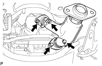
REMOVE TAIL EXHAUST PIPE ASSEMBLY
-
Remove the 2 bolts and 2 compression springs.
-
Disconnect the exhaust pipe support and remove the tail exhaust pipe assembly.
-
Remove the gasket from the center exhaust pipe assembly.
-
-
REMOVE CENTER EXHAUST PIPE ASSEMBLY
-
Remove the 2 bolts and 2 compression springs.
-
Disconnect the 3 exhaust pipe supports and remove the center exhaust pipe assembly.
-
Remove the gasket from the No. 3 exhaust pipe sub-assembly.
-
-
REMOVE FRONT NO. 3 EXHAUST PIPE SUB-ASSEMBLY
-
Remove the 3 clamps and disconnect the heated oxygen sensor (for bank 1 sensor 2) connector.
-
Remove the 2 bolts, 2 nuts and front No. 3 exhaust pipe sub-assembly.
-
Remove the 2 gaskets from the front No. 3 exhaust pipe sub-assembly.
-
-
REMOVE FRONT EXHAUST PIPE ASSEMBLY
-
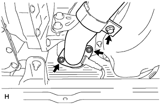
Loosen the bolt.
-
Remove the 2 nuts and front exhaust pipe assembly.
-
Remove the gasket from the front exhaust pipe assembly.
-
-
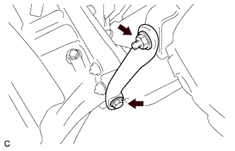
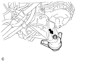
DISCONNECT FRONT STABILIZER LINK ASSEMBLY LH
-
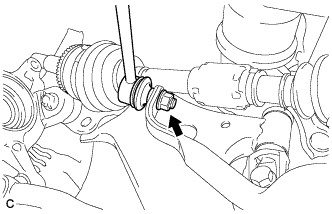
Remove the nut and separate the front stabilizer link assembly LH.
Tech Tips
If the ball joint turns together with the nut, use a hexagon wrench (6 mm) to hold the stud bolt.
-
-
DISCONNECT FRONT STABILIZER LINK ASSEMBLY RH
Tech Tips
Use the same procedure described for the LH side.
-
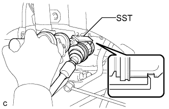
REMOVE FRONT AXLE HUB NUT LH
-
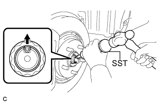
Using SST and a hammer, release the staked part of the front axle hub nut.
- SST
- 09930-00010
Note
Loosen the staked part of the nut completely, otherwise the threads of the drive shaft may be damaged.
-
While applying the brakes, remove the front axle hub nut.
-
-
REMOVE FRONT AXLE HUB NUT RH
Tech Tips
Perform the same procedure for the LH side.
-
DISCONNECT FRONT SPEED SENSOR LH
-
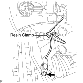
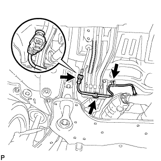
Remove the bolt and resin clamp, and separate the front speed sensor.
-
-
DISCONNECT FRONT SPEED SENSOR RH
Tech Tips
Use the same procedure described for the LH side.
-
DISCONNECT TIE ROD ASSEMBLY LH
-
Remove the cotter pin and the nut.
-
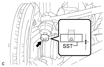
Install SST to the tie rod end.
- SST
- 09960-20010 ( 09961-02060 )
Note
Make sure that the upper ends of the tie rod end and SST are aligned.
-
Using SST, separate the tie rod end from the steering knuckle.
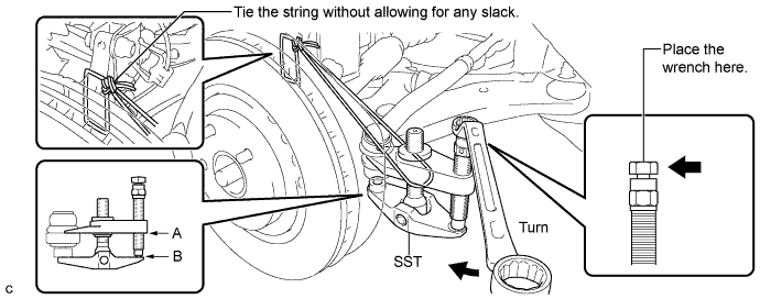
- SST
- 09960-20010 ( 09961-02010 )
Note
-
When securing SST to the steering knuckle, be sure to tighten the string of SST to prevent it from falling.
-
Install SST so that A and B are parallel.
-
Be sure to place the wrench on the part indicated in the illustration.
-
Do not damage the front disc brake dust cover.
-
Do not damage the ball joint dust cover.
-
Do not damage the steering knuckle.
-
-
DISCONNECT TIE ROD ASSEMBLY RH
Tech Tips
Use the same procedure described for the LH side.
-
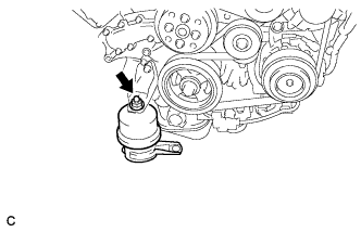
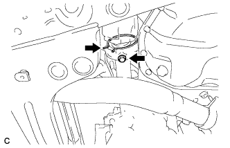
SEPARATE NO. 1 FRONT SUSPENSION LOWER ARM LH
-
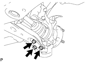
Remove the bolt, 2 nuts, and separate the front lower suspension arm from the lower ball joint.
-
-
SEPARATE NO. 1 FRONT SUSPENSION LOWER ARM RH
Tech Tips
Use the same procedure described for the LH side.
-
SEPARATE FRONT AXLE ASSEMBLY LH
-
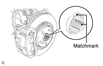
Put matchmarks on the front drive shaft assembly and the front axle hub sub-assembly.
Note
Do not punch the marks.
-
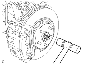
Using a plastic hammer, separate the front drive shaft assembly from the front axle assembly.
Note
Be careful not to damage the drive shaft boot and speed sensor rotor.
-
-
SEPARATE FRONT AXLE ASSEMBLY RH
Tech Tips
Use the same procedure described for the LH side.
-
DISCONNECT STEERING INTERMEDIATE SHAFT SUB-ASSEMBLY
-
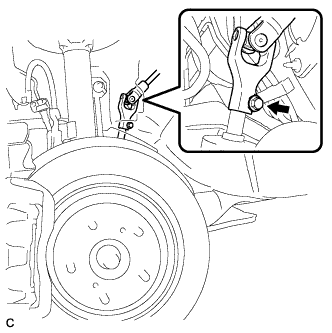
Remove the bolt and slide the steering intermediate shaft assembly.
Note
Do not separate the steering intermediate shaft assembly from the power steering link assembly.
-
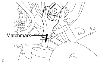
Put matchmarks on the steering intermediate shaft assembly and the power steering link assembly.
-
Separate the steering intermediate shaft assembly from the power steering link assembly.
-
-
DISCONNECT DISCHARGE HOSE SUB-ASSEMBLY
-
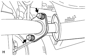
Remove the bolt and disconnect the discharge hose sub-assembly from the compressor and magnetic clutch.
-
Remove the O-ring from the discharge hose sub-assembly.
Note
Seal the openings of the disconnected parts using vinyl tape to prevent entry of moisture and foreign matter.
-
-
DISCONNECT SUCTION HOSE SUB-ASSEMBLY
-
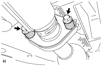
Remove the bolt and disconnect the suction hose sub-assembly from the compressor and magnetic clutch.
-
Remove the O-ring from the suction hose sub-assembly.
Note
Seal the openings of the disconnected parts using vinyl tape to prevent entry of moisture and foreign matter.
-
-
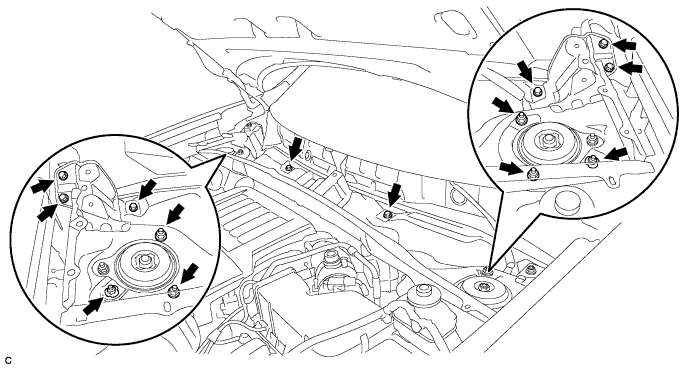
REMOVE ENGINE ASSEMBLY WITH TRANSAXLE
-
Set the engine lifter.
-
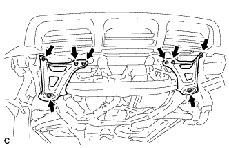
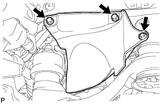
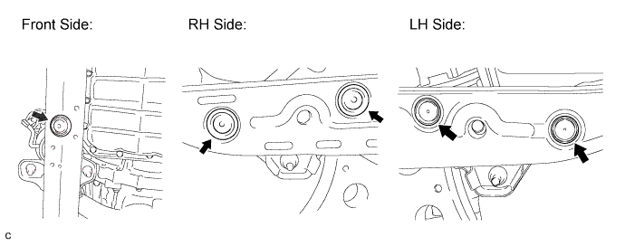
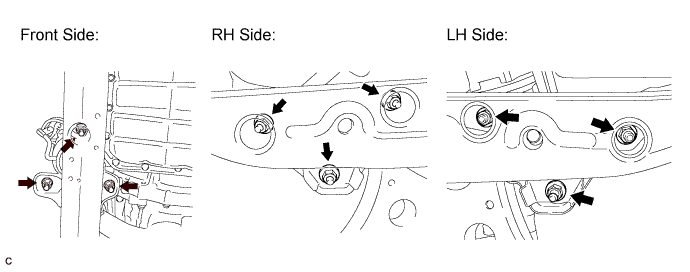
Remove the 6 bolts, 2 nuts, and frame side rail plates RH and LH.
-
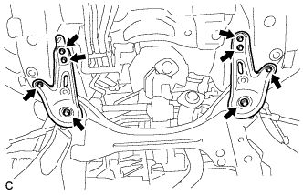
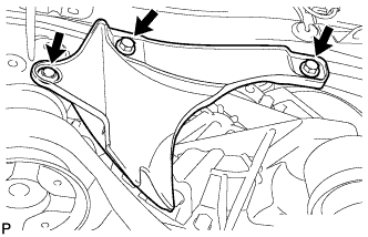
Remove the 6 bolts, 2 nuts, and front suspension member rear braces RH and LH.
-
Operate the engine lifter, then remove the engine assembly from the vehicle.
Note
Make sure that the engine is clear of all wiring and hoses.
-
-
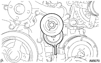
REMOVE V-RIBBED BELT
-
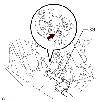
Using SST, release the V-ribbed belt tension by turning the V-ribbed belt tensioner assembly counterclockwise, and remove the V-ribbed belt from the V-ribbed belt tensioner assembly.
- SST
- 09961-00950
-
While turning the V-ribbed belt tensioner assembly counterclockwise, align with its holes, and then insert the 5 mm bi-hexagon wrench into the holes to fix the V-ribbed belt tensioner assembly.
-
-
REMOVE FRONT STABILIZER BAR
Tech Tips
-
REMOVE POWER STEERING LINK ASSEMBLY
-
Remove the 2 bolts, 2 nuts, and power steering link assembly.
Note
Because the nut has its own stopper, do not turn the nut. Loosen the bolt with the nut fixed.
-
-
REMOVE COMPRESSOR AND MAGNETIC CLUTCH
-
Disengage the clamp.
-
Disconnect the connector.
-
Disengage each clamp.
-
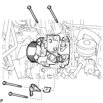
Remove the 4 bolts, compressor and magnetic clutch.
-
-
REMOVE VENTILATION HOSE
-
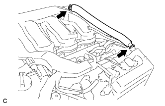
Using pliers, grip the claws of the 2 clips and slide the 2 clips to remove the ventilation hose.
-
-
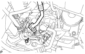
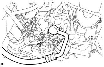
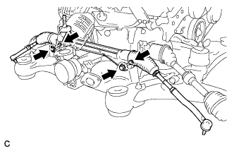
REMOVE INTAKE AIR SURGE TANK ASSEMBLY
-
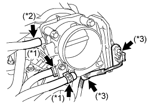
Disconnect the 2 water by-pass hoses from the throttle with motor body assembly (*1).
-
Disconnect the vapor feed hose (*2).
-
Disconnect the throttle with motor body assembly connector and clamp (*3).
-
Disconnect the No. 1 ventilation hose.
-
Disconnect the connector.
-
Remove the 4 bolts, No. 1 surge tank stay and throttle body bracket.
-
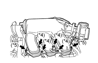
Using a 5 mm socket hexagon wrench, remove the 4 bolts (*4).
-
Remove the 2 nuts and intake air surge tank (*5).
-
Remove the gasket from the intake air surge tank.
-
-
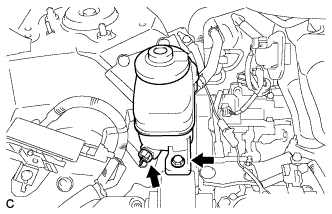
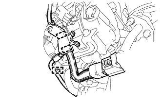
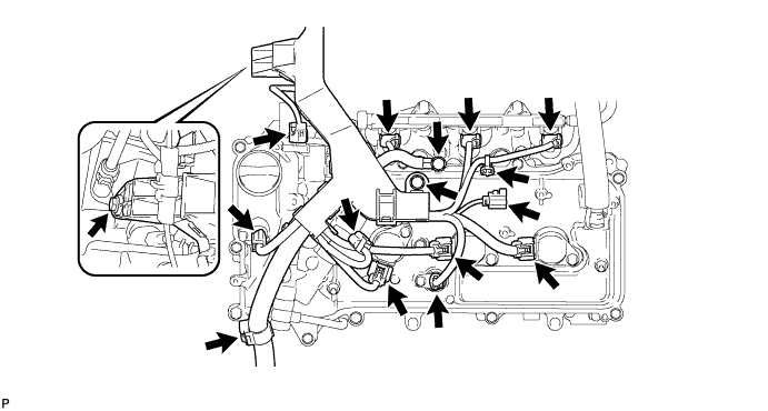
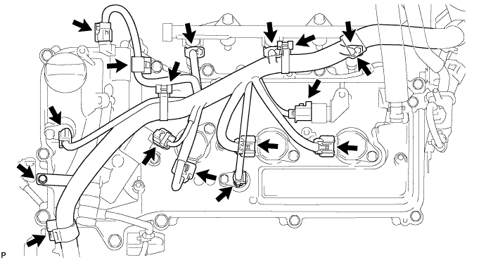
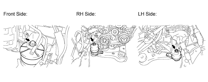
REMOVE ENGINE WIRE (for LHD)
-
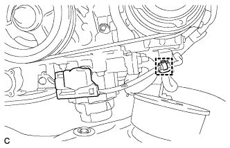
Disconnect the oil pressure switch cover and clamp.
-
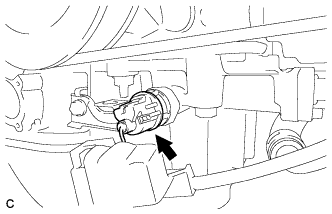
Disconnect the oil pressure switch assembly connector.
-
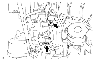
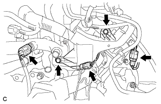
Disconnect the crankshaft position sensor connector and clamp.
-
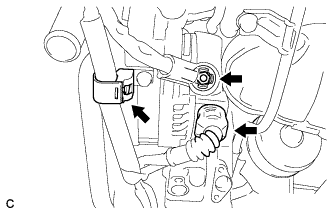
Disconnect the generator assembly connector and clamp.
-
Remove the nut and separate the engine wire from the generator assembly.
-
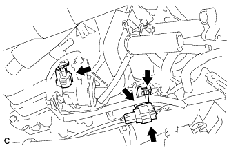
Disconnect the purge VSV connector, air fuel ratio sensor connector and 2 clamps.
-
Remove the bolt.
-
Disconnect the engine coolant temperature sensor connector, knock control sensor wire connector and 2 clamps.
-
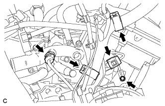
Disconnect the air fuel ratio sensor connector and clamp.
-
Remove the bolt and 2 nuts.
-
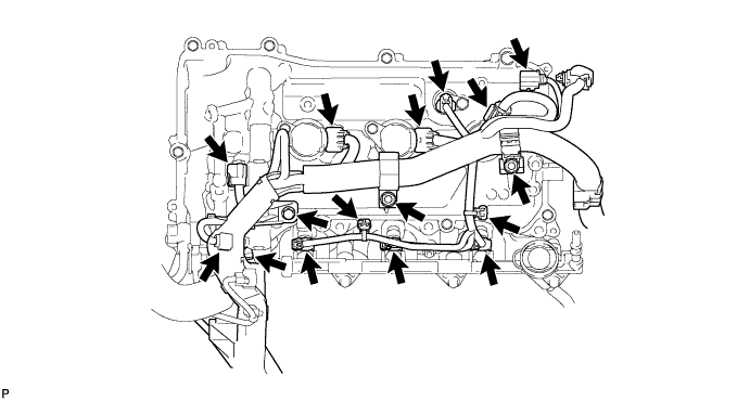
Disconnect the 2 clamps, radio setting condenser connector, 3 ignition coil assembly connectors, 2 camshaft timing oil control valve assembly connectors, 2 VVT sensor connectors and 3 injector assembly connectors, and separate the engine wire from the cylinder head cover sub-assembly RH.
-
Remove the 3 bolts.
-
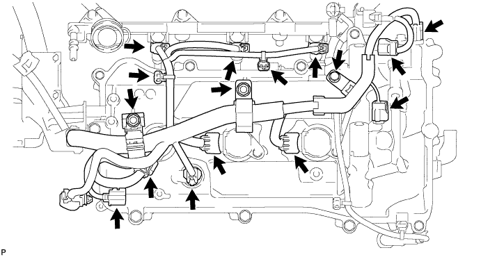
Disconnect the 2 clamps, radio setting condenser connector, 3 ignition coil assembly connectors, 2 camshaft timing oil control valve assembly connectors, 2 VVT sensor connectors and 3 injector assembly connectors, and separate the engine wire from the engine assembly.
-
-
REMOVE ENGINE WIRE (for RHD)
-
Disconnect the oil pressure switch cover and clamp.
-
Disconnect the oil pressure switch assembly connector.
-
Disconnect the crankshaft position sensor connector and clamp.
-
Disconnect the generator assembly connector and clamp.
-
Remove the nut, and separate the engine wire from the generator assembly.
-
Disconnect the purge VSV connector, air fuel ratio sensor connector and 2 clamps.
-
Remove the 2 bolts.
-
Disconnect the engine coolant temperature sensor connector, knock control sensor wire connector and clamp.
-
Disconnect the air fuel ratio sensor connector and clamp.
-
Remove the bolt and 2 nuts.
-
Disconnect the 2 clamps, radio setting condenser connector, 3 ignition coil assembly connectors, 2 camshaft timing oil control valve assembly connectors, 2 VVT sensor connectors and 3 injector assembly connectors, and separate the engine wire from the cylinder head cover sub-assembly RH.
-
Remove the bolt.
-
Disconnect the 5 clamps, radio setting condenser connector, 3 ignition coil assembly connectors, 2 camshaft timing oil control valve assembly connectors, 2 VVT sensor connectors and 3 injector assembly connectors, and separate the engine wire from the engine assembly.
-
-
REMOVE STARTER ASSEMBLY
-
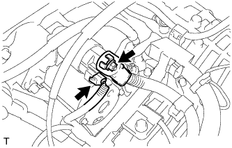
Disconnect the starter connector.
-
Open the terminal cap, remove the nut and disconnect the starter wire.
-
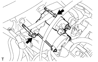
Remove the 2 bolts and starter.
-
-
REMOVE TRANSVERSE ENGINE MOUNTING BRACKET
-
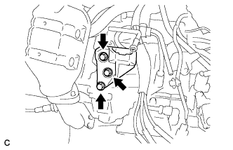
Remove the 3 bolts and transverse engine mounting bracket.
-
-
REMOVE MANIFOLD STAY
-
Remove the bolt, nut, and manifold stay.
-
-
INSTALL ENGINE HANGERS
-
Install the 2 engine hangers with the 4 bolts as shown in the illustration.
Part No. No. 1 engine hanger 12281-31120 No. 2 engine hanger 12282-31100 Bolts 91671-10825 - Torque:
- 33 N*m { 337 kgf*cm, 24 ft.*lbf }
-
Attach the engine sling device and hang the engine with the chain block.
-
-
REMOVE FRONT FRAME ASSEMBLY
-
Disconnect the active mount VSV connector and harness clamp.
-
Loosen the bolt and 2 nuts.
-
Remove the 5 hole plugs.
-
Remove the 9 nuts.
-
Remove the 2 bolts and separate the engine with transaxle from the front frame assembly.
-
-
REMOVE FRONT ENGINE MOUNTING INSULATOR ASSEMBLY
-
Remove the bolt and front engine mounting insulator assembly.
-
-
REMOVE TRANSVERSE ENGINE MOUNTING INSULATOR
-
Remove the nut and transverse engine mounting insulator.
-
-
REMOVE TRANSVERSE ENGINE MOUNTING INSULATOR
-
Remove the nut and transverse engine mounting insulator.
-
-
REMOVE FRONT DRIVE SHAFT ASSEMBLY LH
-
Using SST, remove the front drive shaft assembly LH.
- SST
- 09520-01010
- 09520-24010 ( 09520-32040 )
Note
-
Be careful not to damage the drive shaft dust cover, boot, or oil seal.
-
Be careful not to drop the drive shaft assembly.
-
-
REMOVE FRONT DRIVE SHAFT ASSEMBLY RH (for 2WD)
-
Remove the bearing bracket hole snap ring from the drive shaft bearing bracket.
-
Remove the bolt and front drive shaft assembly RH from the drive shaft bearing bracket.
Note
Do not damage the boot or oil seal.
-
-
REMOVE NO. 2 TRANSMISSION CONTROL CABLE BRACKET
-
Remove the bolt and the transmission control cable bracket.
-
-
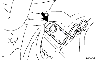
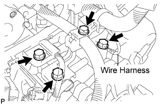
REMOVE WIRE HARNESS CLAMP
-
Remove the bolt and disconnect the wire harness.
-
Remove the 3 bolts and 3 clamps.
-
-
DISCONNECT WIRE HARNESS
-
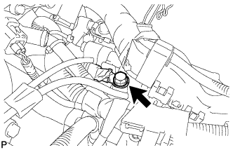
Remove the bolt and disconnect the wire harness.
-
-
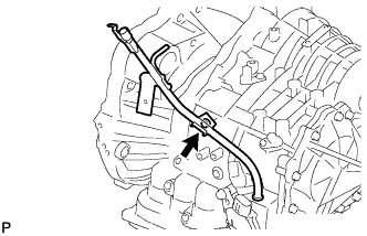
REMOVE BREATHER PLUG HOSE
-
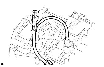
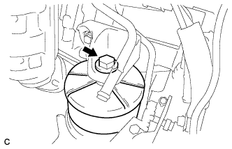
Disconnect the breather plug hose from the oil filler tube.
-
-
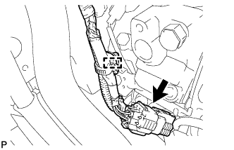
DISCONNECT CONNECTORS
-
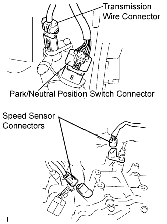
Disconnect the transmission wire connector.
-
Disconnect the park/neutral position switch connector.
-
Disconnect the 2 speed sensor connectors.
-
-
REMOVE NO. 1 TRANSMISSION CONTROL CABLE BRACKET
-
Remove the 2 bolts and No. 1 transmission control cable bracket.
-
-
REMOVE NO. 1 OIL COOLER INLET TUBE
-
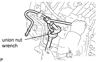
Using union nut wrench (17 mm) and a wrench, disconnect the No. 1 oil cooler inlet tube.
-
-
REMOVE NO. 1 OIL COOLER OUTLET TUBE
-
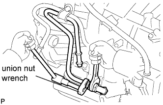
Using union nut wrench (17 mm) and a wrench, disconnect the No. 1 oil cooler outlet tube.
-
-
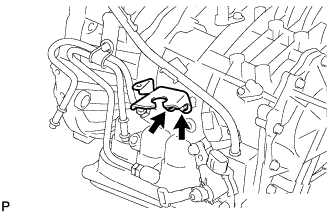
REMOVE TRANSMISSION OIL FILTER TUBE SUB-ASSEMBLY
-
Remove the ATF level gauge.
-
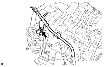
Remove the bolt and oil cooler tube clamp.
-
Remove the bolt and transmission oil filter tube sub-assembly.
-
Remove the O-ring from the oil filter tube sub-assembly.
-
-
REMOVE AUTOMATIC TRANSAXLE ASSEMBLY
-
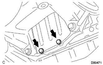
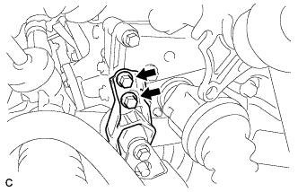
Remove the 2 bolts and bracket with the flywheel housing under cover.
-
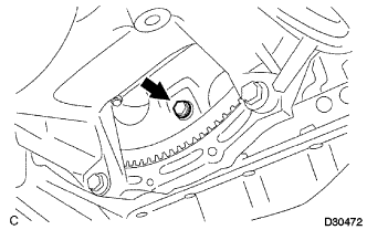
Turn the crankshaft to gain access and remove the 6 bolts while holding the crankshaft pulley bolt with a wrench.
Note
One of the 6 bolts has a different color than the other ones.
-
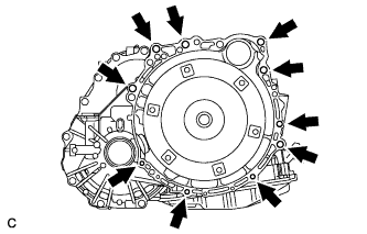
Remove the 10 bolts.
-
Separate and remove the automatic transaxle.
-
-
REMOVE TORQUE CONVERTER CLUTCH ASSEMBLY
-
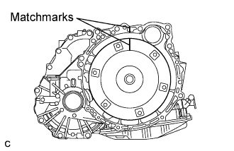
Put matchmarks on the transmission case and torque converter clutch assembly.
-
Remove the torque converter clutch assembly from the automatic transaxle assembly.
-
-
INSPECT TORQUE CONVERTER CLUTCH ASSEMBLY
Tech Tips