- Click here
INSTALL SHIFT LEVER ASSEMBLY
-
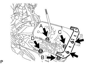
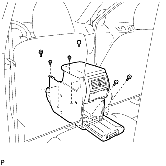
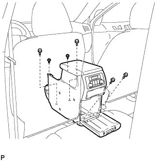
Install the shift lever assembly with the 4 nuts.
12 N*m 122 kgf*cm 9 ft.*lbf Tip:Tighten the nuts in the order of A, B, C, and D.
Note:Be careful not to route the indicator light or shift lock system wiring between the shift lever assembly and the floor while installing the shift lever assembly.
-
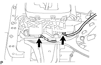
Install the No. 2 console box mounting bracket with the 2 screws.
-
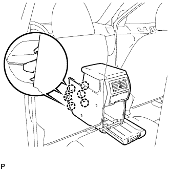
Connect the 2 connectors to the shift lever assembly.
-
- Click here
CONNECT TRANSMISSION CONTROL CABLE ASSEMBLY
-
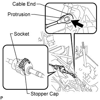
Connect the socket of the transmission control cable assembly to the shift lever assembly.
-
Connect the control cable end to the shift lever assembly.
-
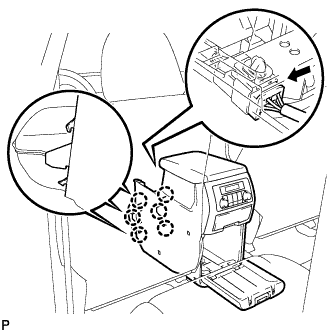
Push the stopper cap to the socket as shown in the illustration.
-
Turn the socket of the transmission control cable assembly clockwise and install the stopper cap.
Note:
-
To prevent torsion of the inner cable, the end with protrusion should face up.
-
Confirm that the connection between the socket and the shift lock control unit is secure.
-
-
- Click here
INSTALL SHIFT LEVER KNOB SUB-ASSEMBLY
-
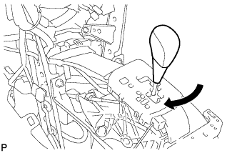
Install the shift lever knob sub-assembly.
-
- Click here
INSTALL FRONT NO. 2 CONSOLE BOX INSERT (for LHD)
-
Engage the claw and 2 guides.
-
Install the front No. 2 console box insert with the 3 screws <F> and clip.
-
- Click here
INSTALL FRONT NO. 2 CONSOLE BOX INSERT (for RHD)
-
Engage the claw and 2 guides.
-
Install the front No. 2 console box insert with the 3 screws <F> and clip.
-
- Click here
INSTALL FRONT NO. 1 CONSOLE BOX INSERT (for LHD)
-
Engage the claw and 2 guides.
-
Install the front No. 1 console box insert with the 3 screws <F> and 2 clips.
-
- Click here
INSTALL FRONT NO. 1 CONSOLE BOX INSERT (for RHD)
-
Engage the claw and 2 guides.
-
Install the front No. 1 console box insert with the 3 screws <F> and clip.
-
- Click here
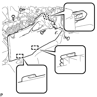
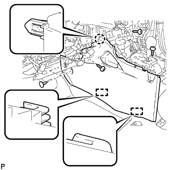
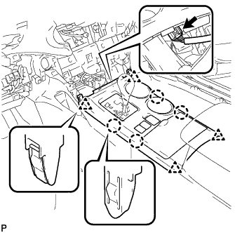
INSTALL CONSOLE BOX ASSEMBLY (w/o Rear Air Conditioning System)
-
Engage the 6 claws.
-
Install the console box assembly with the 4 bolts and 2 screws.
-
- Click here
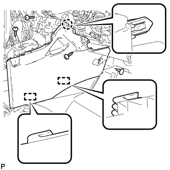
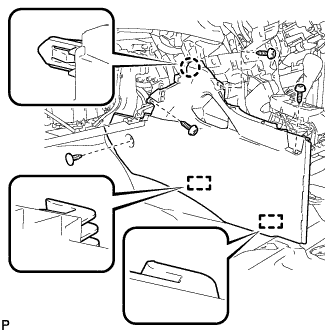
INSTALL CONSOLE BOX ASSEMBLY (w/ Rear Air Conditioning System)
-
Engage the 6 claws.
-
Connect the connector.
-
Install the console box assembly with the 4 bolts and 2 screws.
-
- Click here
INSTALL LOWER REAR CONSOLE BOX
-
Install the lower rear console box.
-
- Click here
INSTALL NO. 2 CONSOLE BOX DUCT (w/o Rear Air Conditioning System)
-
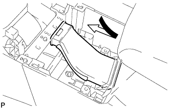
Install the No. 2 console box duct as shown in the illustration.
-
- Click here
INSTALL UPPER CONSOLE PANEL SUB-ASSEMBLY
-
Connect the connector.
-
Engage the 4 claws and 4 clips, and install the upper console panel sub-assembly.
-
- Click here
INSTALL LOWER INSTRUMENT PANEL SUB-ASSEMBLY
-
Connect each connector and clamp.
-
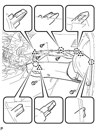
Engage the 4 claws and 3 clips.
-
Install the lower instrument panel sub-assembly with the 2 bolts <B> and 3 screws <F>.
-
- Click here
INSTALL NO. 2 INSTRUMENT PANEL UNDER COVER SUB-ASSEMBLY
-
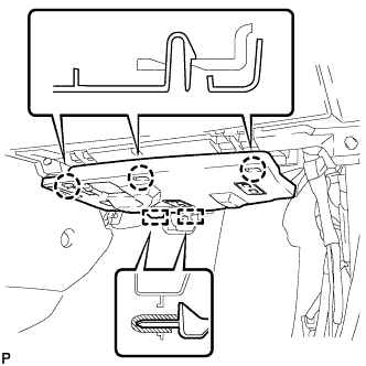
Engage the 2 guides.
-
Engage the 3 claws and install the No. 2 instrument panel under cover sub-assembly.
-
- Click here
INSTALL COWL SIDE TRIM SUB-ASSEMBLY RH
Tip:Use the same procedure for the RH side and the LH side.
- Click here
INSTALL FRONT DOOR SCUFF PLATE RH
Tip:Use the same procedure for the RH side and the LH side.
- Click here
INSTALL LOWER INSTRUMENT PANEL FINISH PANEL SUB-ASSEMBLY (for Manual Air Conditioning System)
-

Connect the hood lock control cable assembly.
-
Connect each connector.
-
Engage the 3 claws and 10 clips.
-
Install the lower instrument panel finish panel sub-assembly with the 2 bolts <B>.
-
- Click here
INSTALL LOWER INSTRUMENT PANEL FINISH PANEL SUB-ASSEMBLY (for Automatic Air Conditioning System)
-

Connect the hood lock control cable assembly.
-
Connect each connector and the aspirator duct.
-

Engage the 3 claws and 10 clips.
-
Install the lower instrument panel finish panel sub-assembly with the 2 bolts <B>.
-
- Click here
INSTALL COWL SIDE TRIM SUB-ASSEMBLY LH
-

Engage the claw and clip, install the cowl side trim sub-assembly LH.
-
Install the clip.
-
- Click here
INSTALL FRONT DOOR SCUFF PLATE LH
-

Engage the guide and the 8 claws, and install the front door scuff plate LH.
-
- Click here
INSTALL CENTER INSTRUMENT CLUSTER FINISH PANEL ASSEMBLY (w/o Smart Entry and Start System)
-

Apply protective tape to the areas shown in the illustration.
-
Connect each connector.
-
Engage the 10 claws and 8 clips, and install the center instrument cluster finish panel assembly.
Note:Do not the damage the instrument panel safety pad assembly and lower instrument panel finish panel sub-assembly.
-
- Click here
INSTALL CENTER INSTRUMENT CLUSTER FINISH PANEL ASSEMBLY (w/ Smart Entry and Start System)
-
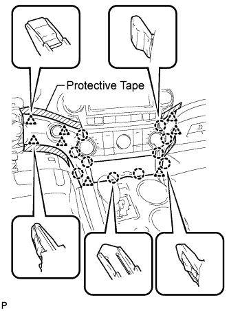
Apply protective tape to the areas shown in the illustration.
-
Connect each connector.
-
Engage the 10 claws and 8 clips, and install the center instrument cluster finish panel assembly.
Note:Do not the damage the instrument panel safety pad assembly and lower instrument panel finish panel sub-assembly.
-
- Click here
CONNECT CABLE TO NEGATIVE BATTERY TERMINAL
Note:When disconnecting the cable, some systems need to be initialized after the cable is reconnected (Click here).
- Click here
ADJUST SHIFT LEVER POSITION
-
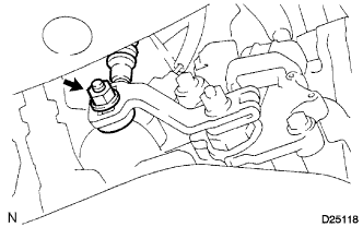
Loosen the nut on the control shaft lever.
-
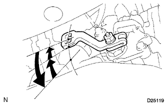
Push the control shaft fully downward.
-
Return the control shaft lever 2 notches to the N position.
-
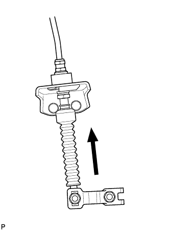
While pushing the control cable end up with the shift lever in the N position, install it to the control shaft lever with the nut.
12 N*m 122 kgf*cm 9 ft.*lbf Note:
-
If the control cable end is excessively pushed up, the shift lever cannot be adjusted.
-
When tightening the nut, confirm that the control cable is properly stretched.
-
-
Start the engine and make sure that the vehicle moves forward when shifting the lever from the N to the D position and moves rearward when shifting it to the R position.
-
- Click here
INSPECT SHIFT LEVER POSITION
-
When shifting from the P to the R position with the ignition switch on (IG) and the brake pedal depressed, make sure that the shift lever moves smoothly and moves correctly into the position.
-
Start the engine and make sure that the vehicle moves forward when shifting from the N to the D position and moves rearward when shifting to the R position. If operation cannot be done as specified, inspect the park/neutral position switch assembly and check the shift lever assembly installation condition.
-