SHIFT LEVER INSTALLATION
-
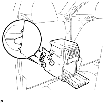
INSTALL SHIFT LEVER ASSEMBLY
-
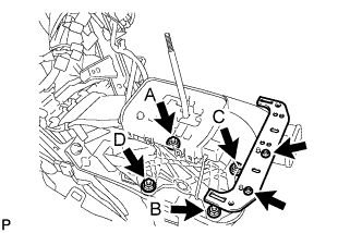
Install the shift lever assembly with the 4 nuts.
- Torque:
- 12 N*m { 122 kgf*cm, 9 ft.*lbf }
Tech Tips
Tighten the nuts in the order of A, B, C, and D.
Note
Be careful not to route the indicator light or shift lock system wiring between the shift lever assembly and the floor while installing the shift lever assembly.
-
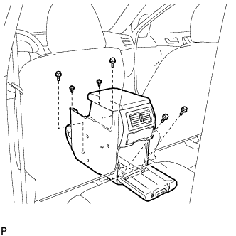
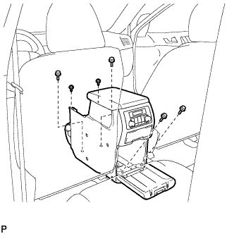
Install the No. 2 console box mounting bracket with the 2 screws.
-
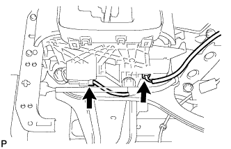
Connect the 2 connectors to the shift lever assembly.
-
-
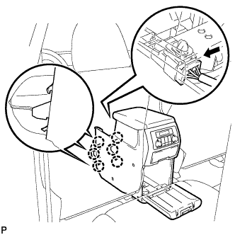
CONNECT TRANSMISSION CONTROL CABLE ASSEMBLY
-
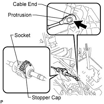
Connect the socket of the transmission control cable assembly to the shift lever assembly.
-
Connect the control cable end to the shift lever assembly.
-
Push the stopper cap to the socket as shown in the illustration.
-
Turn the socket of the transmission control cable assembly clockwise and install the stopper cap.
Note
-
To prevent torsion of the inner cable, the end with protrusion should face up.
-
Confirm that the connection between the socket and the shift lock control unit is secure.
-
-
-
INSTALL SHIFT LEVER KNOB SUB-ASSEMBLY
-
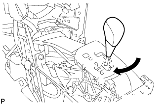
Install the shift lever knob sub-assembly.
-
-
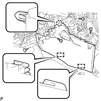
INSTALL FRONT NO. 2 CONSOLE BOX INSERT (for LHD)
-
Engage the claw and 2 guides.
-
Install the front No. 2 console box insert with the 3 screws <E> and clip.
-
-
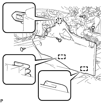
INSTALL FRONT NO. 2 CONSOLE BOX INSERT (for RHD)
-
Engage the claw and 2 guides.
-
Install the front No. 2 console box insert with the 3 screws <E> and clip.
-
-
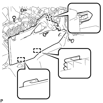
INSTALL FRONT NO. 1 CONSOLE BOX INSERT (for LHD)
-
Engage the claw and 2 guides.
-
Install the front No. 1 console box insert with the 3 screws <E> and 2 clips.
-
-
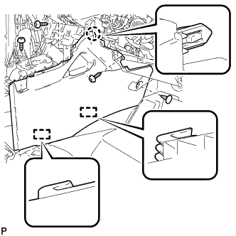
INSTALL FRONT NO. 1 CONSOLE BOX INSERT (for RHD)
-
Engage the claw and 2 guides.
-
Install the front No. 1 console box insert with the 3 screws <E> and clip.
-
-
INSTALL CONSOLE BOX ASSEMBLY (w/o Rear Air Conditioning System)
-
Engage the 6 claws.
-
Install the console box assembly with the 4 bolts and 2 screws.
-
-
INSTALL CONSOLE BOX ASSEMBLY (w/ Rear Air Conditioning System)
-
Engage the 6 claws.
-
Connect the connector.
-
Install the console box assembly with the 4 bolts and 2 screws.
-
-
INSTALL LOWER REAR CONSOLE BOX
-
Install the lower rear console box.
-
-
INSTALL NO. 2 CONSOLE BOX DUCT (w/o Rear Air Conditioning System)
-
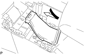
Install the No. 2 console box duct as shown in the illustration.
-
-
INSTALL UPPER CONSOLE PANEL SUB-ASSEMBLY
-
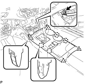
Connect the connector.
-
Engage the 4 claws and 4 clips, and install the upper console panel sub-assembly.
-
-
INSTALL LOWER INSTRUMENT PANEL SUB-ASSEMBLY
-
Connect each connector and clamp.
-
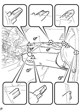
Engage the 4 claws and 3 clips.
-
Install the lower instrument panel sub-assembly with the 2 bolts <B> and 3 screws <E>.
-
-
INSTALL NO. 2 INSTRUMENT PANEL UNDER COVER SUB-ASSEMBLY
-
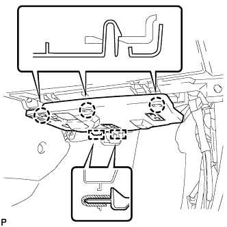
Engage the 2 guides.
-
Engage the 3 claws and install the No. 2 instrument panel under cover sub-assembly.
-
-
INSTALL COWL SIDE TRIM SUB-ASSEMBLY RH
Tech Tips
Use the same procedure for the RH side and the LH side.
-
INSTALL FRONT DOOR SCUFF PLATE RH
Tech Tips
Use the same procedure for the RH side and the LH side.
-
INSTALL LOWER INSTRUMENT PANEL FINISH PANEL SUB-ASSEMBLY (for Manual Air Conditioning System)
-

Connect the hood lock control cable assembly.
-
Connect each connector.
-
Engage the 3 claws and 10 clips.
-
Install the lower instrument panel finish panel sub-assembly with the 2 bolts <B>.
-
-
INSTALL LOWER INSTRUMENT PANEL FINISH PANEL SUB-ASSEMBLY (for Automatic Air Conditioning System)
-

Connect the hood lock control cable assembly.
-
Connect each connector and the aspirator duct.
-

Engage the 3 claws and 10 clips.
-
Install the lower instrument panel finish panel sub-assembly with the 2 bolts <B>.
-
-
INSTALL COWL SIDE TRIM SUB-ASSEMBLY LH
-

Engage the claw and clip, install the cowl side trim sub-assembly LH.
-
Install the clip.
-
-
INSTALL FRONT DOOR SCUFF PLATE LH
-

Engage the guide and 8 claws, and install the front door scuff plate LH.
-
-
INSTALL CENTER INSTRUMENT CLUSTER FINISH PANEL ASSEMBLY (w/o Smart Entry and Start System)
-

Apply protective tape to the areas shown in the illustration.
-
Connect each connector.
-
Engage the 10 claws and 8 clips, and install the center instrument cluster finish panel assembly.
Note
Do not the damage the instrument panel safety pad assembly and lower instrument panel finish panel sub-assembly.
-
-
INSTALL CENTER INSTRUMENT CLUSTER FINISH PANEL ASSEMBLY (w/ Smart Entry and Start System)
-
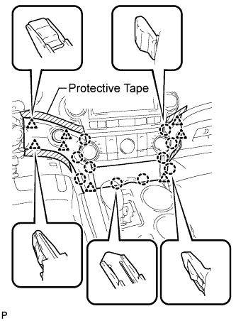
Apply protective tape to the areas shown in the illustration.
-
Connect each connector.
-
Engage the 10 claws and 8 clips, and install the center instrument cluster finish panel assembly.
Note
Do not the damage the instrument panel safety pad assembly and lower instrument panel finish panel sub-assembly.
-
-
CONNECT CABLE TO NEGATIVE BATTERY TERMINAL
Note
When disconnecting the cable, some systems need to be initialized after the cable is reconnected Click here.
-
ADJUST SHIFT LEVER POSITION
-
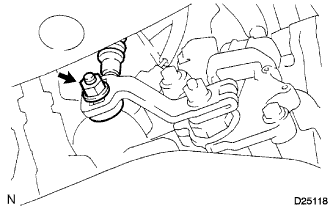
Loosen the nut on the control shaft lever.
-
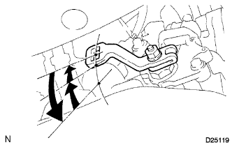
Push the control shaft fully downward.
-
Return the control shaft lever 2 notches to the N position.
-
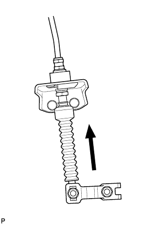
While pushing the control cable end up with the shift lever in the N position, install it to the control shaft lever with the nut.
- Torque:
- 12 N*m { 122 kgf*cm, 9 ft.*lbf }
Note
-
If the control cable end is excessively pushed up, the shift lever cannot be adjusted.
-
When tightening the nut, confirm that the control cable is properly stretched.
-
Start the engine and make sure that the vehicle moves forward when shifting the lever from the N to the D position and moves rearward when shifting it to the R position.
-
-
INSPECT SHIFT LEVER POSITION
-
When shifting from the P to the R position with the ignition switch on (IG) and the brake pedal depressed, make sure that the shift lever moves smoothly and moves correctly into the position.
-
Start the engine and make sure that the vehicle moves forward when shifting from the N to the D position and moves rearward when shifting to the R position. If operation cannot be done as specified, inspect the park/neutral position switch assembly and check the shift lever assembly installation condition.
-