FORWARD CLUTCH REASSEMBLY
-
INSTALL INPUT SHAFT OIL SEAL RING
-
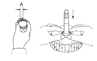
Compress a new input shaft oil seal ring from both sides to reduce dimension A.
Dimension A 5 mm (0.197 in.) -
Coat the oil seal ring with ATF and install it to the input shaft.
Note
Do not expand the end gap of the oil seal ring too much. Fix the hooks firmly.
-
-
INSTALL FORWARD CLUTCH PISTON SUB-ASSEMBLY
-
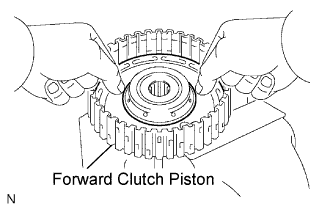
Coat the forward clutch piston with ATF and install it to the input shaft.
Note
Be careful not to damage the lip of the forward clutch piston.
-
-
INSTALL FORWARD CLUTCH RETURN SPRING SUB-ASSEMBLY
-
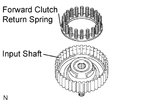
Install the return spring to the input shaft.
Note
After installing the spring sub-assembly, check that all of the springs are engaged in the piston correctly.
-
Coat the clutch balancer with ATF.
-
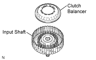
Install the clutch balancer to the input shaft.
Note
-
Be careful not to damage the lip of the forward clutch balancer.
-
Make sure that the clutch balancer is not pinched and that there are no other defects on the lip.
-
Apply sufficient ATF to the sealing lip before installation.
-
-
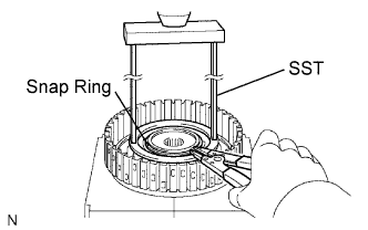
Place SST on the clutch balancer, and compress the clutch balancer with a press.
- SST
- 09387-00020
-
Install the snap ring with a snap ring expander.
-
Be sure that the end gap of the snap ring is not aligned with the spring retainer claw.
Note
-
Stop the press when the spring seat is lowered to the place 1 to 2 mm (0.039 to 0.078 in.) from the snap ring groove. This prevents the spring seat from being deformed.
-
Do not expand the snap ring excessively.
-
-
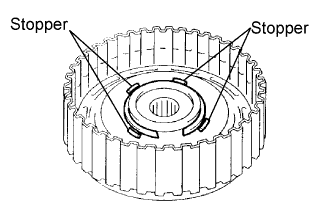
Set the end gap of the snap ring in the piston as shown in the illustration.
Note
The end gap of the snap ring should not align with any of the stoppers.
-
-
INSTALL FORWARD MULTIPLE DISC CLUTCH DISC
-
Coat the 5 discs with ATF.
-
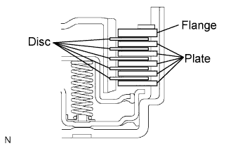
Install the 5 plates, 5 discs, and flange input shaft.
Note
Make sure that the plates, discs, and flange are installed as shown in the illustration.
-
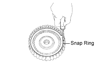
Using a screwdriver, install the snap ring.
-
Check that the end gap of the snap ring is not aligned with one of the cutouts.
Note
The snap ring should be fully engaged in the groove of the drum.
-
-
INSPECT PACK CLEARANCE OF FORWARD CLUTCH
-
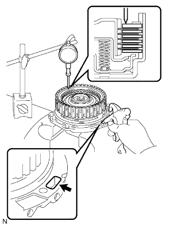
Using a dial indicator, measure the forward clutch pack clearance while applying and releasing compressed air (392 kgf/cm2, 4.0 kPa, 57 psi).
Pack clearance 1.00 to 1.25 mm (0.0394 to 0.0492 in.) If the piston stroke is less than the minimum, the parts may be assembled incorrectly. Check and reassemble the parts again.
If the clearance is not as specified, select another flange.
Tech Tips
There are 5 different thicknesses of flanges available.
Flange thickness: mm (in.) No. Thickness No. Thickness 1 3.00 (0.1181) 4 3.45 (0.1358) 2 3.15 (0.1240) 5 3.60 (0.1417) 3 3.30 (0.1299) - -
-
-
INSPECT FORWARD MULTIPLE DISC CLUTCH DISC
-
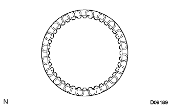
Check if the sliding surface of the disc, plate, and flange are worn or burnt.
If necessary, replace them.
Tech Tips
-
If the lining of the disc comes off or discolors, or if a part of the groove is worn, replace all discs.
-
Before installing new discs, immerse them in ATF for at least 15 minutes.
-
-