FORWARD CLUTCH DISASSEMBLY
-
INSPECT PACK CLEARANCE OF FORWARD CLUTCH
-
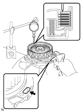
Using a dial indicator, measure the forward clutch pack clearance while applying and releasing compressed air (392 kgf/cm2, 4.0 kPa, 57 psi).
Pack clearance 1.00 to 1.25 mm (0.0394 to 0.0492 in.) If the piston stroke is less than the minimum, the parts may be assembled incorrectly. Check and reassemble the parts again.
If the clearance is not as specified, select another flange.
Tech Tips
There are 5 different thicknesses of flanges available.
Flange thickness: mm (in.) No. Thickness No. Thickness 1 3.00 (0.1181) 4 3.45 (0.1358) 2 3.15 (0.1240) 5 3.60 (0.1417) 3 3.30 (0.1299) - -
-
-
REMOVE FORWARD MULTIPLE DISC CLUTCH DISC
-
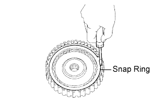
Using a screwdriver, remove the snap ring.
-
Remove the flange, 5 discs, and 5 plates from the input shaft assembly.
-
-
REMOVE FORWARD CLUTCH RETURN SPRING SUB-ASSEMBLY
-
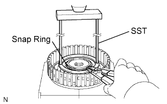
Place SST on the spring retainer and compress the return spring with a press.
- SST
- 09387-00020
-
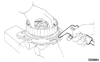
Using a snap ring expander, remove the snap ring.
Note
-
Stop the press when the spring seat is lowered 1 to 2 mm (0.039 to 0.078 in.) from the snap ring groove to prevent the spring seat from being deformed.
-
Do not expand the snap ring excessively.
-
-
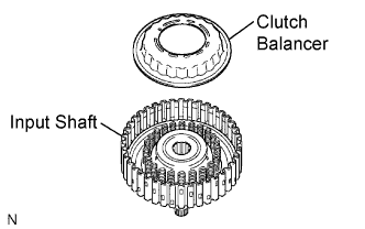
Remove the clutch balancer from the input shaft.
-
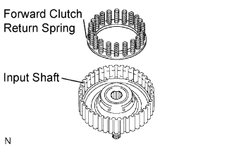
Remove the forward clutch return spring from the input shaft.
-
-
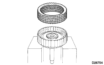
REMOVE FORWARD CLUTCH PISTON SUB-ASSEMBLY
-
Place the forward clutch drum onto the oil pump.
-
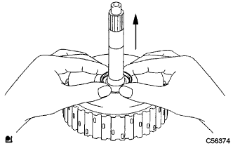
Holding the forward clutch piston by hand, apply compressed air (392 kPa, 4.0 kgf/cm2, 57 psi) to the oil pump to remove the forward clutch piston.
Tech Tips
When the piston cannot be removed as it is slanted, blow air again with the protruding side pushed, or remove the piston using needle nose pliers with its tip taped.
-
-
REMOVE INPUT SHAFT OIL SEAL RING
-
Remove the input shaft oil seal ring from the input shaft.
-