AUTOMATIC TRANSAXLE SYSTEM Pattern Select Switch Circuit
DESCRIPTION
ECT SNOW is the system that operates the throttle motor to control engine output to reduce skidding of the driving wheels, guarantee takeoff acceleration, driving straightness and turning stability.
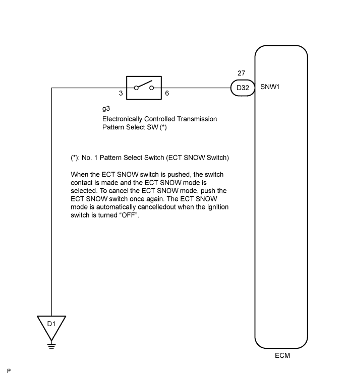
WIRING DIAGRAM
INSPECTION PROCEDURE
PROCEDURE
-
DRIVING TEST
-
Start the engine.
-
Turn the ECT SNOW switch "OFF" (Normal drive mode).
-
Confirm vehicle response by driving from a parked position to fully depressing the accelerator pedal (*1).
-
Turn the ECT SNOW switch "ON" and perform the same check as (*1).
Confirm that there is a difference between ECT SNOW switch "ON" and "OFF".
Tech Tips
-
Driving test should be done on a paved road (a nonskid road).
-
Make sure not to use the VSC system when testing a vehicle equipped with one.
Standard There is a difference in acceleration between "ON" and "OFF". -
NG 
CHECK HARNESS AND CONNECTOR (NO. 1 PATTERN SELECT SWITCH ASSEMBLY - BODY GROUND) Click here
OK 
PROCEED TO NEXT CIRCUIT INSPECTION SHOWN IN PROBLEM SYMPTOMS TABLE
-
-
CHECK HARNESS AND CONNECTOR (NO. 1 PATTERN SELECT SWITCH ASSEMBLY - BODY GROUND)
-
Disconnect the No. 1 pattern select switch (ECT SNOW switch) connector.
-
Measure the resistance according to the value(s) in the table below.
Tech Tips
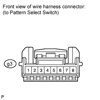
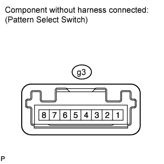
The No. 1 pattern select switch connector has no terminals in locations of 1, 2, 7 and 8.
Standard resistance Tester Connection Condition Specified Condition 3 - Body ground Always Below 1 Ω
NG 
REPAIR OR REPLACE HARNESS OR CONNECTOR
OK 
-
-
INSPECT NO. 1 PATTERN SELECT SWITCH ASSEMBLY
-
Measure the resistance according to the value(s) in the table below.
Tech Tips
The No. 1 pattern select switch connector has no terminals in locations of 1, 2, 7 and 8.
Standard resistance Tester Connection Switch Condition Specified Condition 3 - 6 Press continuously Pattern select switch Below 1 Ω Release Pattern select switch 10 kΩ or higher
NG
REPLACE NO. 1 PATTERN SELECT SWITCH ASSEMBLY
OK
-
-
CHECK HARNESS AND CONNECTOR (NO. 1 PATTERN SELECT SWITCH ASSEMBLY - ECM)
-
Connect the No. 1 pattern select switch (ECT SNOW switch) connector.
-
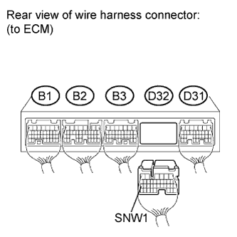
Disconnect the ECM connector.
-
Measure the resistance according to the value(s) in the table below when the shift lever is moved to each position.
Standard resistance Tester Connection Switch Condition Specified Condition D32-27 (SNW1) - Body ground Press continuously Pattern select switch Below 1 Ω Release Pattern select switch 10 kΩ or higher
NG
REPAIR OR REPLACE HARNESS OR CONNECTOR
OK
PROCEED TO NEXT CIRCUIT INSPECTION SHOWN IN PROBLEM SYMPTOMS TABLE
-