AUTOMATIC TRANSAXLE SYSTEM DIAGNOSIS SYSTEM
-
EURO-OBD (EUROPEAN SPEC)

When troubleshooting Europe On-Board Diagnostic (Euro-OBD) vehicles, the vehicle must be connected to an OBD scan tool (complying with ISO 15765-4). Various data output from the vehicle's ECM can then be read.
Euro-OBD regulations require that the vehicle's on-board computer illuminates the Malfunction Indicator Lamp (MIL) on the instrument panel when the computer detects a malfunction in:
-
The emission control system/components
-
The power train control components (which affect vehicle emissions)
-
The computer
In addition, the applicable Diagnostic Trouble Codes (DTCs) prescribed by ISO 15765-4 are recorded in the ECM memory. If the malfunction does not reoccur in 3 consecutive trips, the MIL turns off automatically but the DTCs remain recorded in the ECM memory.
To check DTCs, connect the intelligent tester to the Data Link Connector 3 (DLC3) of the vehicle.
The scan tool displays DTCs, the freeze frame data and a variety of the engine data.
The DTCs and freeze frame data can be erased with the scan tool Click here.
-
-
M-OBD (EXCEPT EUROPEAN SPEC.)
When troubleshooting Multiplex On-Board Diagnostic (M-OBD) vehicle, the vehicle must be connected to intelligent tester. Various data output from the ECM can then be read.
OBD regulations require that the vehicle's on-board computer illuminates the MIL on the instrument panel when the computer detects a malfunction in:
-
The emission control system/components
-
The power train control components (which affect vehicle emissions)
-
The computer
In addition, the applicable DTCs are recorded in the ECM memory. If the malfunction does not recur in 3 consecutive trips, the MIL turns off automatically but the DTCs remain recorded in the ECM memory.
-
-
NORMAL MODE AND CHECK MODE
-
The diagnosis system operates in "normal mode" during the normal vehicle use. In normal mode, "2-trip detection logic" is used to ensure accurate detection of malfunction. "Check mode" is also available to technicians as an option. In check mode, "1-trip detection logic" is used for simulating malfunction symptoms and increasing the system's ability to detect malfunctions, including intermittent malfunction.
-
-
2-TRIP DETECTION LOGIC
-
When a malfunction is first detected, the malfunction is temporarily stored in the ECM memory (1st trip). If the ignition switch is turned off and then turned on (IG) again, and same malfunction is detected again, the MIL will illuminate.
-
-
FREEZE FRAME DATA
-
Freeze frame data records the engine conditions (fuel system, calculated load, engine coolant temperature, fuel trim, engine speed, vehicle speed, etc.) when a malfunction is detected. When troubleshooting, freeze frame data can help determine if the vehicle was running or stopped, if the engine was warmed up or not, if the air-fuel ratio was Lean or Rich, and other data from the time the malfunction occurred.
Tech Tips
If it is impossible to duplicate the problem even though a DTC is detected, confirm the freeze frame data.
-
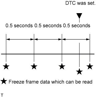
The ECM records engine conditions in the form of freeze frame data every 0.5 seconds. Using intelligent tester, five separate sets of freeze frame data, including the data values at the time when the DTC was set, can be checked.
-
3 data set before the DTC was set.
-
1 data set when the DTC was set.
-
1 data set after the DTC was set.
-
These data sets can be used to simulate the condition of the vehicle around the time of the occurrence of the malfunction. The data may assist in identifying of the cause of the malfunction, and in judging whether it was temporary or not.
-
-
CHECK DLC3
-
Check the DLC3 Click here.
-
-
CHECK BATTERY VOLTAGE
-
Measure the battery voltage.
If voltage is below 11 V, replace the battery before proceeding.
-
-
CHECK MIL
-
The MIL comes on when the ignition switch is turned on (IG) and the engine is not running.
Tech Tips
If the MIL does not light up, troubleshoot the combination meter.
-
When the engine is started, the MIL should go off. If the lamp remains on, it means that the diagnosis system has detected a malfunction or abnormality in the system.
-