Click here
-
ECM
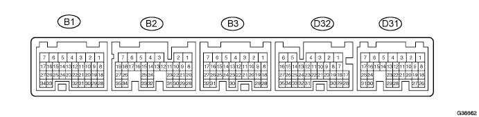
Tip:Each ECM terminal's standard voltage is shown in the table below.
In the table, first follow the information under "Condition". Look under "Terminal No. (Symbols)" for the terminals to inspected. The standard voltage between the terminals is shown under "Specified Condition".
Use the illustration above as a reference for the ECM terminals.
Terminals No. (Symbols) Wiring Color Terminal Description Condition Specified Condition D32-21 (D) - B3-1 (E1) BR - W-B D shift position switch signal Ignition switch on (IG) and shift lever D and S position 11 to 14 V Ignition switch on (IG) and shift lever except D and S position Below 1 V D32-11 (R) - B3-1 (E1) G - W-B R shift position switch signal Ignition switch on (IG) and shift lever R position 11 to 14 V Ignition switch on (IG) and shift lever except R position Below 1 V D32-8 (SPD) - B3-1 (E1) LG - W-B Speed signal Vehicle speed 20 km/h (12 mph) Pulse generation
(See waveform 8)
D31-15 (STP) - B3-1 (E1) R - W-B Stop light switch signal Brake pedal is depressed 7.5 to 14 V Brake pedal is released Below 1.5 V D32-5 (SFTD) - B3-1 (E1) BR - W-B Down shift switch signal Ignition switch on (IG) and shift lever S position 11 to 14 V Ignition switch on (IG) and shift lever "-" position (Down shift) Below 1 V D32-6 (SFTU) - B3-1 (E1) V - W-B Up shift switch signal Ignition switch on (IG) and shift lever S position 11 to 14 V Ignition switch on (IG) and shift lever "+" position (Up shift) Below 1 V D32-20 (S) - B3-1 (E1) SB - W-B S shift position switch signal Ignition switch on (IG) and shift lever S position 11 to 14 V Ignition switch on (IG) and shift lever except S position Below 1 V D32-23 (P) - B3-1 (E1) LG - W-B Park position switch signal Ignition switch on (IG) and shift lever P position 11 to 14 V Ignition switch on (IG) and shift lever except P position Below 1 V D32-22 (N) - B3-1 (E1) R - W-B Neutral position switch signal Ignition switch on (IG) and shift lever N position 11 to 14 V Ignition switch on (IG) and shift lever except N position Below 1 V B2-8 (NSW (STAR)) - B3-1 (E1) GR - W-B Park neutral switch signal Ignition switch on (IG) and shift lever P and N position Below 1 V Ignition switch on (IG) and shift lever except P and N position 11 to 14 V B2-11 (DSL) - B3-1 (E1) B - W-B DSL solenoid signal Vehicle speed 65 km/h (40 mph), lock-up (ON to OFF) Pulse generation
(See waveform 2)
B2-9 (SR) - B3-1 (E1) Y - W-B SR solenoid signal Ignition switch on (IG) Below 1 V 3rd, 4th or 5th gear 11 to 14 V 1st or 2nd gear Below 1 V B2-10 (S4) - B3-1 (E1) L - W-B S4 solenoid signal Ignition switch on (IG) Below 1 V 5th gear 11 to 14 V Except 5th gear Below 1 V B2-17 (SL3+) - B2-16 (SL3-) W - G SL3 solenoid signal Engine idle speed Pulse generation
(See waveform 3)
B2-15 (SL2+) - B2-14 (SL2-) Y - L SL2 solenoid signal Engine idle speed Pulse generation
(See waveform 4)
B2-19 (SL1+) - B2-18 (SL1-) G - GR SL1 solenoid signal Engine idle speed Pulse generation
(See waveform 5)
B2-34 (NC+) - B2-26 (NC-) R - BR Speed sensor (NC) signal Vehicle speed 30 km/h (19 mph): (3rd gear)
Engine speed 1400 rpm
Pulse generation
(See waveform 6)
B2-35 (NT+) - B2-27 (NT-) W - L Speed sensor (NT) signal Vehicle speed 20 km/h (12 mph) Pulse generation
(See waveform 7)
B2-13 (SLT+) - B2-12 (SLT-) R - G SLT solenoid signal Engine idle speed Pulse generation
(See waveform 1)
B2-24 (THO1) - B1-28 (E2) P - BR ATF temperature sensor signal ATF temperature: 115°C (239°F) or more Below 1.5 V D32-27 (SNW1) - B3-1 (E1) V - W-B ECT SNOW switch signal Ignition switch on (IG) 11 to 14 V Ignition switch on (IG) and press continuously pattern select switch (ect snow switch) Below 1 V
-
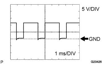
Waveform 1
Table 1. Reference: Terminal SLT+ - SLT- Tool setting 5 V/DIV, 1 ms/DIV Vehicle condition Engine idle speed -
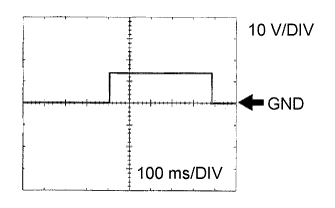
Waveform 2
Table 2. Reference: Terminal DSL - E1 Tool setting 10 V/DIV, 100 ms/DIV Vehicle condition Vehicle speed 65 km/h (40 mph), lock-up (ON to OFF) -
Waveform 3
Table 3. Reference: Terminal SL3+ - SL3- Tool setting 5 V/DIV, 1 ms/DIV Vehicle condition Engine idle speed -
Waveform 4
Table 4. Reference: Terminal SL2+ - SL2- Tool setting 5 V/DIV, 1 ms/DIV Vehicle condition Engine idle speed -

Waveform 5
Table 5. Reference: Terminal SL1+ - SL1- Tool setting 5 V/DIV, 1 ms/DIV Vehicle condition Engine idle speed -
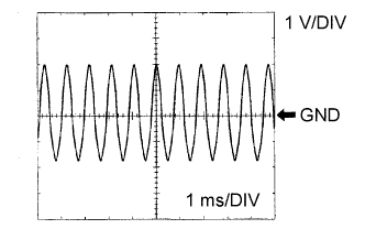
Waveform 6
Table 6. Reference: Terminal NC+ - NC- Tool setting 1 V/DIV, 1 ms/DIV Vehicle condition Vehicle speed 30 km/h (19 mph): (3rd gear)
Engine speed 1400 rpm
-
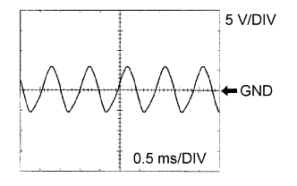
Waveform 7
Table 7. Reference: Terminal NT+ - NT- Tool setting 5 V/DIV, 0.5 ms/DIV Vehicle condition Vehicle speed 20 km/h (12 mph) -
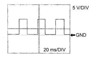
Waveform 8
Table 8. Reference: Terminal SPD - E1 Tool setting 5 V/DIV, 20 ms/DIV Vehicle condition Vehicle speed 20 km/h (12 mph)
-