| DTC Code | DTC Name |
|---|---|
| Engine does not Start |
DESCRIPTION
Click here
-
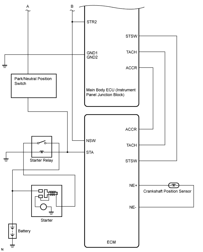
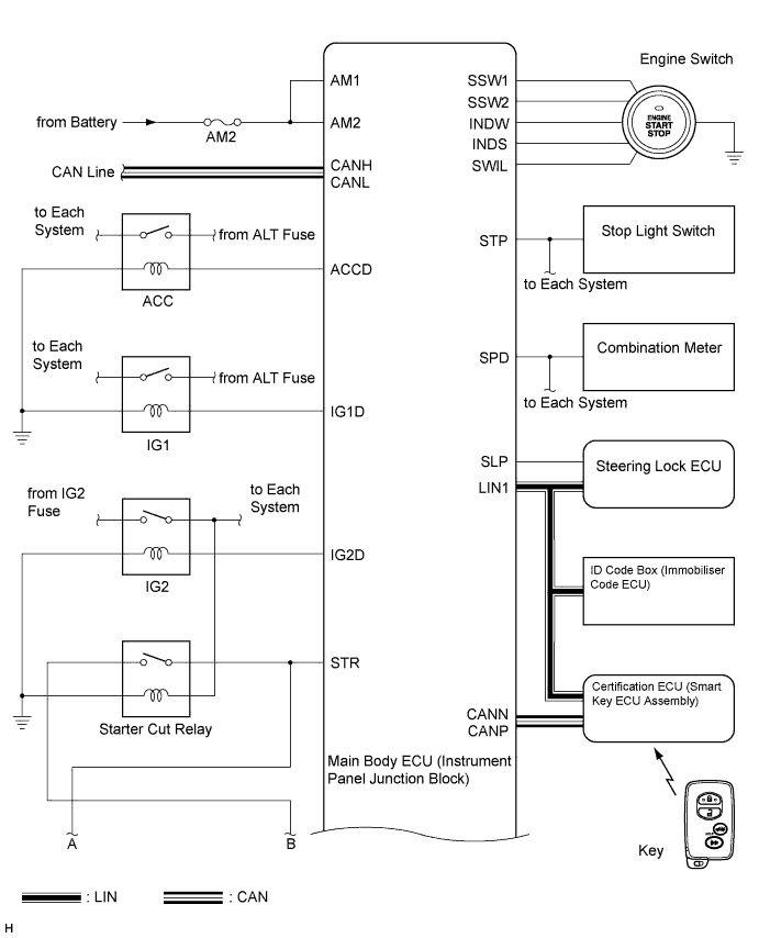
ENGINE START SYSTEM FUNCTION
-
If the engine switch is pressed with the shift lever is in the P or N position and the brake pedal depressed, the main body ECU determines that it is an engine start request.
-
The certification ECU (smart key ECU assembly) and other ECUs perform key verification via the LIN communication line.
-
The main body ECU activates the ACC relay.
-
The main body ECU activates the IG1 and IG2 relays.
-
The certification ECU (smart key ECU assembly) outputs a steering UNLOCK signal. The signal is sent to the main body ECU via the steering lock ECU.
-
The main body ECU sends an engine start request signal to the ECM.
-
The ECM sends an ACC cut request signal to the main body ECU.
-
The ECM and main body ECU activate the starter relay.
-
The main body ECU deactivates the ACC relay until the main body ECU detects an engine start.
-
When engine revolution speed reaches 1200 rpm, the ECM determines that the engine has been started.
Symbol of main body ECU Signal STP Stop light switch ON signal Input SSW1/SSW2 Engine switch ON signal Input ACCD ACC relay operation signal Output SLP Steering lock actuator position signal Input IG1D IG1 relay operation signal Output IG2D IG2 relay operation signal Output STR2 Starter relay operation signal (Sub) Output STR Park/Neutral position switch signal Input TACH Engine start detection signal Input STSW Starter activation request signal Output ACCR ACC cut request signal Input Symbol of ECM Signal ACCR ACC cut request signal Output TACH Engine revolution speed signal Output STSW Starter activation request signal Input STAR Starter relay operation signal (Main) Output STA Starter activation signal Input
-
INSPECTION PROCEDURE
Click here
-
EMERGENCY ENGINE START CONTROL
-
If there is a malfunction in the stop light switch circuit or STOP fuse, their signals may not be correctly transmitted to the main body ECU. This may result in the engine not starting even if the engine switch is pressed while the brake pedal is depressed and the shift lever is in the P position.
To activate the starter:
-
Turn the engine switch from off to on (ACC).
-
Press and hold the engine switch for 15 seconds.
-
Tip:If the main body ECU is replaced with a new one while the negative (-) battery terminal is connected, the power source mode will be in IG-ON mode. When the battery is removed and reinstalled, the power source mode that was selected when the battery was removed is restored.
After the main body ECU, certification ECU (smart key ECU assembly), steering lock ECU, ID code box (immobiliser code ECU) and/or ECM are/is replaced, perform the registration procedure for the engine immobiliser system.
-
PROCEDURE
- Click here
CHECK THE ENGINE SWITCH CONDITION
-
Check that the power source mode changes.
-
When the key is inside the vehicle and the shift lever is in the P position, check that the power source mode changes.
OK off → on (ACC) → on (IG) → off
-
- OKClick here
- NGClick here
-
- Click here
CHECK DTC
-
Delete the DTCs (Click here).
-
Check for DTCs again.
-
Proceed to the next step based on the inspection result.
Result Result Proceed to No DTC is output A Smart entry and start system (starting function) DTCs are output B Steering lock DTCs are output C Engine immobiliser system DTCs are output D Vehicle stability control system DTCs are output E
-
- Click here
CHECK CRANKING FUNCTION
-
Check the engine cranking function.
-
When there is fuel in the fuel tank, the key is inside the vehicle, and the shift lever is in the P position, check that depressing the brake pedal and pressing the engine switch crank the engine.
Result Result Proceed to Engine cranks A Engine does not crank B
-
-
- Click here
READ VALUE USING INTELLIGENT TESTER (STARTER CONTROL)
-
Connect the intelligent tester to the DLC3.
-
Turn the engine switch on (IG).
-
Read the DATA LIST according to the displays on the tester screen.
Table 1. ECM: Tester Display Measurement Item/Range Normal Condition Diagnostic Note Starter Control Starter switch signal / ON or OFF ON: Engine switch on (ST)
OFF: Engine switch except on (ST)
- Standard Engine switch condition Tester display When engine switch is on (ST) ON When engine switch is except on (ST) OFF
- OKClick here
- NGClick here
-
- Click here
PERFORM ACTIVE TEST USING INTELLIGENT TESTER (STARTER RELAY)
-
Connect the intelligent tester to the DLC3.
-
Turn the engine switch on (IG).
-
Perform Active Test according to the prompts displayed on the tester.
Table 2. ECM: Tester Display Test Part Control Range Diagnostic Note Activate the Starter Relay Starter ON or OFF - -
Measure the voltage according to the value(s) in the table below.
Standard voltage Tester Connection Condition Specified Condition Starter relay terminal 2 - Starter relay terminal 1 When starter relay is ON by Active test using intelligent tester 8 to 14 V Starter relay terminal 2 - Starter relay terminal 1 When starter relay is OFF by Active test using intelligent tester Below 1 V
- OKClick here
- NGClick here
-
- Click here
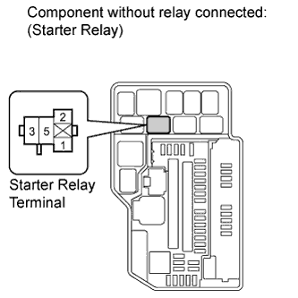
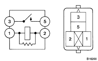
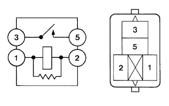
INSPECT STARTER RELAY
-
Remove the starter relay from the engine room relay block.
-
Measure the resistance according to the value(s) in the table below.
Standard resistance Tester Connection Condition Specified Condition 3 - 5 When battery voltage is not applied to terminals 1 and 2 10 kΩ or higher 3 - 5 When battery voltage is applied to terminals 1 and 2 Below 1 Ω
- OKClick here
- NGClick here
-
- Click here
CHECK HARNESS AND CONNECTOR (STARTER RELAY TERMINAL VOLTAGE AND RESISTANCE)
-
Measure the voltage according to the value(s) in the table below.
Standard voltage Tester Connection Condition Specified Condition Starter relay terminal 5 - Body ground Always 11 to 14 V -
Measure the resistance according to the value(s) in the table below.
Standard resistance Tester Connection Condition Specified Condition Starter relay terminal 1 - Body ground Always Below 1 Ω
- OKClick here
- NGClick here
-
- Click here
CHECK HARNESS AND CONNECTOR (STARTER RELAY - STARTER)
-
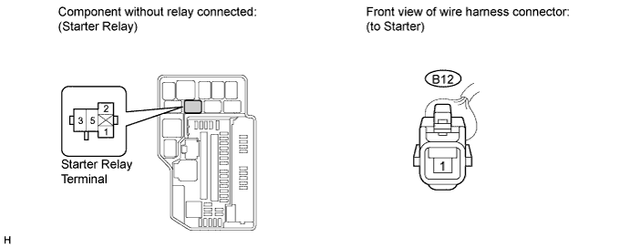
Disconnect the B12 connector.
-
Measure the resistance according to the value(s) in the table below.
Standard resistance Tester Connection Condition Specified Condition Engine room relay block starter relay terminal 3 - B12-1 Always Below 1 Ω Engine room relay block starter relay terminal 3 or B12-1 - Body ground Always 10 kΩ or higher
- OKClick here
- NGClick here
-
- Click here
CHECK HARNESS AND CONNECTOR (BATTERY - STARTER)
-
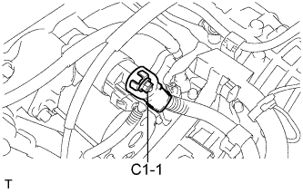
Disconnect the C1 connector.
-
Measure the voltage according to the value(s) in the table below.
Standard voltage Tester Connection Condition Specified Condition C1-1 - Body ground Always 11 to 14 V
- OKClick here
- NGClick here
-
- Click here
READ VALUE USING INTELLIGENT TESTER (PARK/NEUTRAL POSITION SWITCH)
-
Connect the intelligent tester to the DLC3.
-
Turn the engine switch on (IG).
-
Read the DATA LIST according to the displays on the tester screen.
Table 3. Body: Tester Display Measurement Item/Range Normal Condition Diagnostic Note N SW / C SW Park/Neutral position switch / ON or OFF ON: Shift position is P or N
OFF: Shift position is not P or N
- OK "ON" (Shift position is P or N) and "OFF" (Shift position is not P or N) appear on the screen.
- OKClick here
- NGClick here
-
- Click here
READ VALUE USING INTELLIGENT TESTER (S CODE)
-
Connect the intelligent tester to the DLC3.
Tip:When using the intelligent tester with the engine switch off, turn on and off any of the door courtesy light switches repeatedly at 1.5 second intervals or less until communication between the tester and vehicle starts.
-
Turn the engine switch on (IG).
Table 4. Entry & Start: Tester Display Measurement Item/Range Normal Condition Diagnostic Note S Code Chk S code check / OK or NG OK: Normal
NG: Malfunction
- OK "OK" is displayed on the screen.
- OKClick here
- NGClick here
-
- Click here
READ VALUE USING INTELLIGENT TESTER (L CODE)
-
Connect the intelligent tester to the DLC3.
Tip:When using the intelligent tester with the engine switch off, turn on and off any of the door courtesy light switches repeatedly at 1.5 second intervals or less until communication between the tester and vehicle starts.
-
Turn the engine switch on (IG).
Table 5. Entry & Start: Tester Display Measurement Item/Range Normal Condition Diagnostic Note L Code Chk L code check / OK or NG OK: Normal
NG: Malfunction
- OK "OK" is displayed on the screen.
- OKClick here
- NGClick here
-
- Click here
READ VALUE USING INTELLIGENT TESTER (IMMOBILISER SYSTEM STATUS)
-
Connect the intelligent tester to the DLC3.
Tip:When using the intelligent tester with the engine switch off, turn on and off any of the door courtesy light switches repeatedly at 1.5 second intervals or less until communication between the tester and vehicle starts.
-
Turn the engine switch on (IG).
Table 6. Immobiliser: Tester Display Measurement Item/Range Normal Condition Diagnostic Note Immobiliser Immobiliser system status / SET or UNSET UNSET: Engine switch ON
SET: Without key
- OK UNSET (Engine switch ON) appears on the screen.
- OKClick here
- NGClick here
-
- Click here
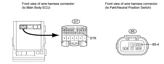
CHECK HARNESS AND CONNECTOR (MAIN BODY ECU - BODY GROUND)
-
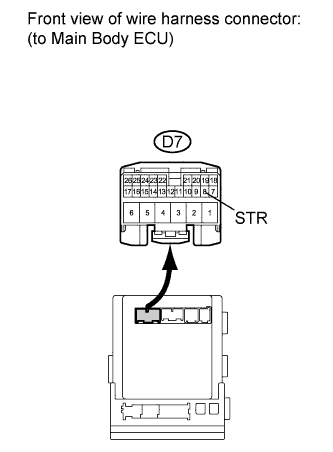
Disconnect the D7 connector from the main body ECU.
-
Measure the resistance according to the value(s) in the table below.
Standard resistance Tester Connection Condition Specified Condition D7-8 (STA) - Body ground Shift position is P or N 105 to 115 Ω D7-8 (STA) - Body ground Shift position is not P nor N 10 kΩ or higher
- OKClick here
- NGClick here
-
- Click here
INSPECT PARK/NEUTRAL POSITION SWITCH
-
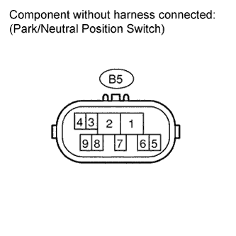
Disconnect the B5 connector.
-
Measure the resistance according to the value(s) in the table below.
Standard resistance Tester Connection Condition Specified Condition 4 - 5 P Below 1 Ω 4 - 5 N Below 1 Ω 4 - 5 Except P and N 10 kΩ or higher
- OKClick here
- NGClick here
-
- Click here
CHECK HARNESS AND CONNECTOR (MAIN BODY ECU - PARK/NEUTRAL POSITION SWITCH)
-
Measure the resistance according the the value(s) in the table below.
Standard resistance Tester Connection Condition Specified Condition D7-8 (STR) - B5-4 Always Below 1 Ω D7-8 (STA) or B5-4 - Body ground Always 10 kΩ or higher
- OKClick here
- NGClick here
-
- Click here
CHECK HARNESS AND CONNECTOR (PARK/NEUTRAL POSITION SWITCH - ECM)
-
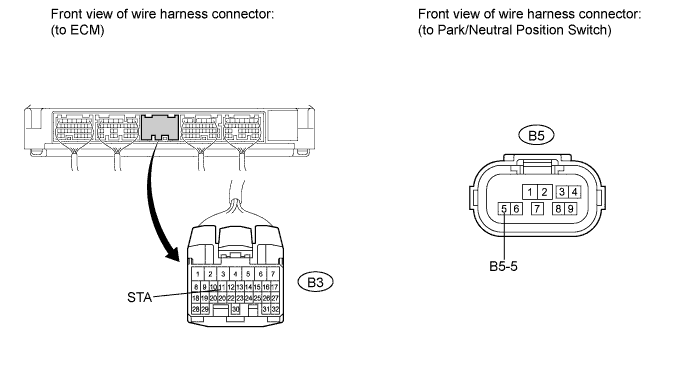
Disconnect the B3 connector from the ECM.
-
Measure the resistance according to the value(s) in the table below.
Standard resistance Tester Connection Condition Specified Condition B5-5 - B3-11 (STA) Always Below 1 Ω B5-5 or B3-11 (STA) - Body ground Always 10 kΩ or higher
- OKClick here
- NGClick here
-
- Click here
INSPECT STARTER RELAY
-
Remove the starter relay from engine room relay block.
-
Measure the resistance according to the value(s) in the table below.
Standard resistance Tester Connection Condition Specified Condition 3 - 5 When battery voltage is not applied to terminals 1 and 2 10 kΩ or higher 3 - 5 When battery voltage is applied to terminals 1 and 2 Below 1 Ω
- OKClick here
- NGClick here
-
- Click here
CHECK HARNESS AND CONNECTOR (ECM - STARTER RELAY)
-
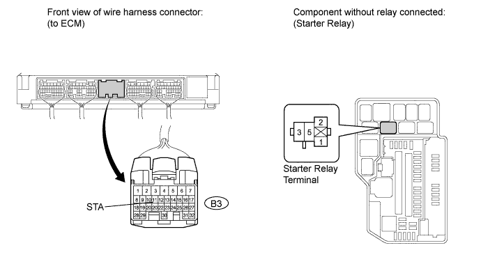
Measure the resistance according to the value(s) in the table below.
Standard resistance Tester Connection Condition Specified Condition Engine room relay block starter relay terminal 2 - B3-11 (STA) Always Below 1 Ω Engine room relay block starter relay terminal 2 or B3-11 (STA) - Body ground Always 10 kΩ or higher
- OKClick here
- NGClick here
-
- Click here
INSPECT STARTER CUT RELAY
-
Remove the starter cut relay from the engine room relay block.
-
Measure the resistance according to the value(s) in the table below.
Standard resistance Tester Connection Condition Specified Condition Engine room relay block starter relay terminal 2 - B3-11 (STA) Always Below 1 Ω Engine room relay block starter relay terminal 2 or B3-11 (STA) - Body ground Always 10 kΩ or higher
- OKClick here
- NGClick here
-
- Click here
CHECK HARNESS AND CONNECTOR (STARTER CUT RELAY - ECM)
-
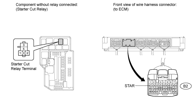
Disconnect the B2 connector from the ECM.
-
Measure the resistance according to the value(s) in the table below.
Standard resistance Tester Connection Condition Specified Condition Engine room relay block starter cut relay terminal 5 - B2-8 (STAR) Always Below 1 Ω Engine room relay block starter cut relay terminal 5 or B2-8 (STAR) - Body ground Always 10 kΩ or higher
- OKClick here
- NGClick here
-
- Click here
CHECK HARNESS AND CONNECTOR (STARTER CUT RELAY - MAIN BODY ECU)
-
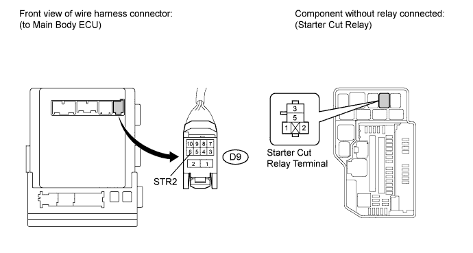
Disconnect the D9 connector from the main body ECU.
-
Measure the resistance according to the value(s) in the table below.
Standard resistance Tester Connection Condition Specified Condition Engine room relay block starter cut relay terminal 5 - D9-6 (STR2) Always Below 1 Ω Engine room relay block starter cut relay terminal 5 or D9-6 (STR2) - Body ground Always 10 kΩ or higher
- OKClick here
- NGClick here
-
- Click here
CHECK HARNESS AND CONNECTOR (ECM - STARTER RELAY)
-
Measure the resistance according to the value(s) in the table below.
Standard resistance Tester Connection Condition Specified Condition Engine room relay block starter relay terminal 2 - B3-11 (STA) Always Below 1 Ω Engine room relay block starter relay terminal 2 or B3-11 (STA) - Body ground Always 10 kΩ or higher
- OKClick here
- NGClick here
-
- Click here
ECU CODE REGISTRATION
-
Register the ECU code.
- NEXTClick here
-
- Click here
CHECK CRANKING FUNCTION
-
Check the engine cranking function.
-
When there is fuel in the fuel tank, the key is inside the vehicle, and the shift lever is in the P position, check that depressing the brake pedal and pressing the engine switch cranks the engine.
Result Result Proceed to Engine does not crank A Engine cranks B
-
-
- Click here
REPLACE CERTIFICATION ECU (SMART KEY ECU)
-
Replace the certification ECU (smart key ECU assembly).
- NEXTClick here
-
- Click here
KEY REGISTRATION
-
Register the key.
- NEXTClick here
-
- Click here
CHECK CRANKING FUNCTION
-
Check the engine cranking function.
-
When there is fuel in the fuel tank, the key is inside the vehicle, and the shift lever is in the P position, check that depressing the brake pedal and pressing the engine switch cranks the engine.
Result Result Proceed to Engine does not crank A Engine cranks B
-
-
- Click here
ECU CODE REGISTRATION
-
Register the ECU code.
- NEXTClick here
-
- Click here
CHECK CRANKING FUNCTION
-
Check the engine cranking function.
-
When there is fuel in the fuel tank, the key is inside the vehicle, and the shift lever is in the P position, check that depressing the brake pedal and pressing the engine switch cranks the engine.
Result Result Proceed to Engine does not crank A Engine cranks B
-
-
- Click here
REPLACE STEERING LOCK ECU
-
Replace the steering lock ECU (Click here).
- NEXTClick here
-
- Click here
ECU CODE REGISTRATION
-
Register the ECU code.
- NEXTClick here
-
- Click here
CHECK CRANKING FUNCTION
-
Check the engine cranking function.
-
When there is fuel in the fuel tank, the key is inside the vehicle, and the shift lever is in the P position, check that depressing the brake pedal and pressing the engine switch cranks the engine.
Result Result Proceed to Engine does not crank A Engine cranks B
-
-
- Click here
READ VALUE USING INTELLIGENT TESTER (ENGINE START REQUEST)
-
Connect the intelligent tester to the DLC3.
Tip:When using the intelligent tester with the engine switch off, turn on and off any of the door courtesy light switches repeatedly at 1.5 second intervals or less until communication between the tester and vehicle starts.
-
Turn the engine switch on (IG).
Table 7. Smart key: Tester Display Measurement Item/Range Normal Condition Diagnostic Note Start Rqst Start request signal response / OK or NG OK: Received
NG: Not received
- OK "OK" (received) and "NG" (not received) appear on the screen.
- OKClick here
- NGClick here
-
- Click here
GO TO OTHER FLOW CHARTClick here
- Click here
GO TO DIAGNOSTIC TROUBLE CODE CHART (SMART ENTRY AND START SYSTEM (STARTING))Click here
- Click here
GO TO DIAGNOSTIC TROUBLE CODE CHART (STEERING LOCK SYSTEM)Click here
- Click here
GO TO DIAGNOSTIC TROUBLE CODE CHART (ENGINE IMMOBILISER SYSTEM)Click here
- Click here
GO TO DIAGNOSTIC TROUBLE CODE CHART (VEHICLE STABILITY CONTROL SYSTEM)Click here
- Click here
GO TO SFI SYSTEMClick here
- Click here
REPLACE STARTER RELAY
- Click here
REPAIR OR REPLACE HARNESS OR CONNECTOR, OR REPLACE FUSE
- Click here
REPAIR OR REPLACE HARNESS OR CONNECTOR (STARTER RELAY - STARTER)
- Click here
REPAIR OR REPLACE HARNESS OR CONNECTOR (BATTERY - STARTER)
- Click here
REPLACE STARTER ASSEMBLYClick here
- Click here
REPLACE MAIN BODY ECU (INSTRUMENT PANEL JUNCTION BLOCK)
- Click here
REPLACE MAIN BODY ECU (INSTRUMENT PANEL JUNCTION BLOCK)
- Click here
REPLACE PARK/NEUTRAL POSITION SWITCHClick here
- Click here
REPAIR OR REPLACE HARNESS OR CONNECTOR (MAIN BODY ECU - PARK/NEUTRAL POSITION SWITCH)
- Click here
REPAIR OR REPLACE HARNESS OR CONNECTOR (PARK/NEUTRAL POSITION SWITCH - ECM)
- Click here
REPLACE STARTER RELAY
- Click here
REPAIR OR REPLACE HARNESS OR CONNECTOR (ECM - STARTER RELAY)
- Click here
REPAIR OR REPLACE HARNESS OR CONNECTOR (STARTER RELAY - BODY GROUND)
- Click here
REPLACE STARTER CUT RELAY
- Click here
REPAIR OR REPLACE HARNESS OR CONNECTOR (STARTER CUT RELAY - ECM)
- Click here
REPAIR OR REPLACE HARNESS OR CONNECTOR (STARTER CUT RELAY - MAIN BODY ECU)
- Click here
REPAIR OR REPLACE HARNESS OR CONNECTOR (ECM - STARTER RELAY)
- Click here
REPLACE ECMClick here
- Click here
END (ECU CODE DEFECTIVE)
- Click here
END
- Click here
REPLACE ID CODE BOX (IMMOBILISER CODE ECU)
- Click here
END
- Click here
END
- Click here
REPLACE ID CODE BOX (IMMOBILISER CODE ECU)
- Click here
REPLACE CERTIFICATION ECU (SMART KEY ECU ASSEMBLY)
- Click here
REPLACE ID CODE BOX (IMMOBILISER CODE ECU)