SMART ENTRY AND START SYSTEM Power Source Mode does not Change
DESCRIPTION
When the engine switch is pushed with the electrical key in the cabin, the main body ECU receives signals to switch the power source mode.
Tech Tips
To allow use of the intelligent tester to inspect the push-button starting function when the engine switch is off, repeat opening and closing any of the doors. Opening and closing a door establishes communication between the intelligent tester and the main body ECU. (Opening and closing a door can also be simulated by operating a door courtesy light switch.)
WIRING DIAGRAM
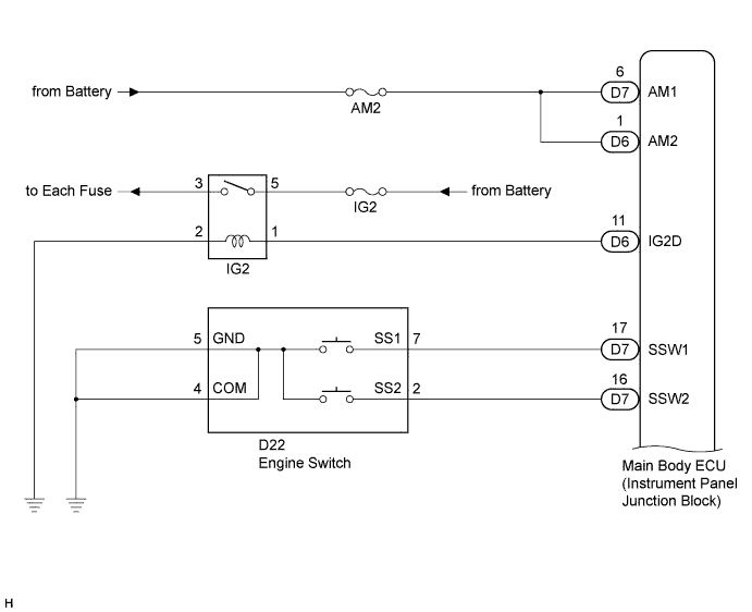
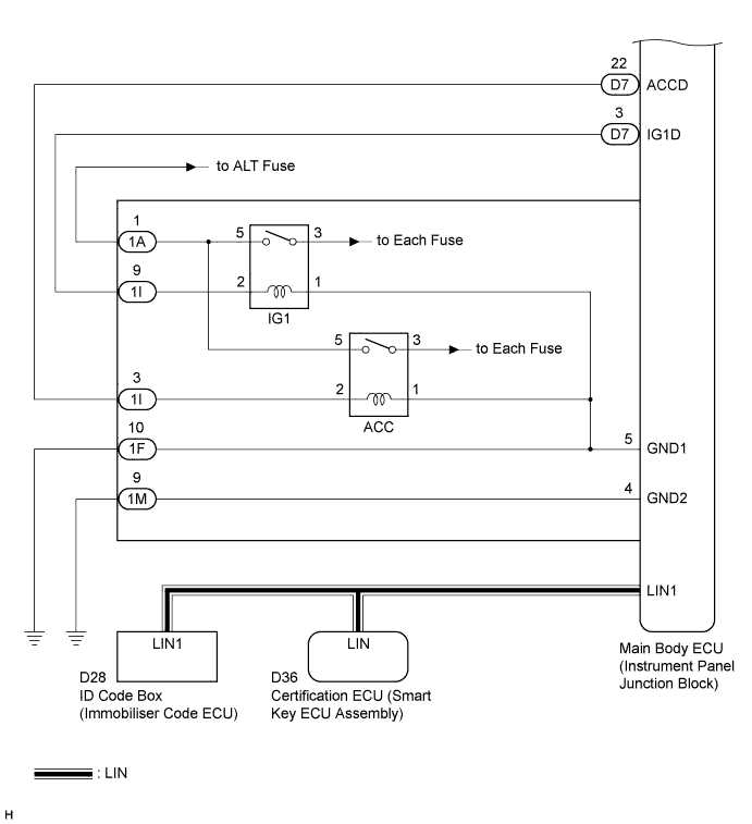
INSPECTION PROCEDURE
PROCEDURE
-
CHECK SMART ENTRY AND START SYSTEM
-
Remove the battery of the electrical key transmitter Click here.
-
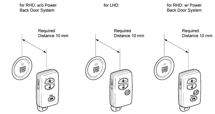
Touch the logo side of the key or card key to the engine switch.
-
Check that power source mode can be changed to on (IG and ACC).
Result Result Proceed to Power source mode does not change to on (ACC) A Power source mode does not change to on (IG) B Power source mode does not change to on (IG and ACC) C Power source mode is turned on D
B 
INSPECT IG1 RELAY Click here
C
CHECK HARNESS AND CONNECTOR (BATTERY - INSTRUMENT PANEL JUNCTION BLOCK) Click here
D 
GO TO SMART ENTRY AND START SYSTEM (ENTRY) Click here
A 
-
-
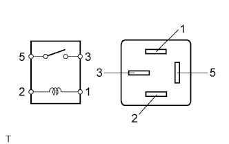
INSPECT ACC RELAY
-
Remove the ACC relay from the instrument panel junction block.
-
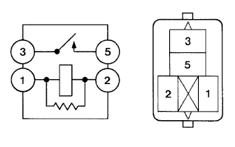
Measure the resistance according to the value(s) in the table below.
Standard resistance Tester Connection Condition Specified condition 3 - 5 When battery voltage is not applied to terminals 1 and 2 10 kΩ or higher 3 - 5 When battery voltage is applied to terminals 1 and 2 Below 1 Ω
NG
REPLACE ACC RELAY
OK
-
-
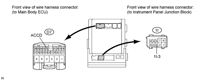
CHECK HARNESS AND CONNECTOR (MAIN BODY ECU - INSTRUMENT PANEL JUNCTION BLOCK)
-
Disconnect the D7 connector from the main body ECU.
-
Disconnect the 1I connector from the instrument panel junction block.
-
Measure the resistance according to the value(s) in the table below.
Standard resistance Tester Connection Condition Specified condition D7-22 (ACCD) - 1I-3 Always Below 1 Ω D7-22 (ACCD) or 1I-3 - Body ground Always 10 kΩ or higher
NG
REPAIR OR REPLACE HARNESS OR CONNECTOR
OK 
REPLACE MAIN BODY ECU (INSTRUMENT PANEL JUNCTION BLOCK)
-
-
INSPECT IG1 RELAY
-
Remove the IG1 relay from the instrument panel junction block.
-
Measure the resistance according to the value(s) in the table below.
Standard resistance Tester connection Condition Specified condition 3 - 5 When battery voltage is not applied to terminals 1 and 2 10 kΩ or higher 3 - 5 When battery voltage is applied to terminal 1 and 2 Below 1 Ω
NG
REPLACE IG1 RELAY
OK
-
-
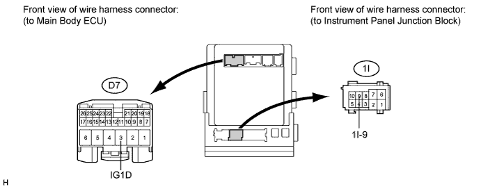
CHECK HARNESS AND CONNECTOR (MAIN BODY ECU - INSTRUMENT PANEL JUNCTION BLOCK)
-
Disconnect the D7 connector from the main body ECU.
-
Disconnect the 1I connector from the instrument panel junction block.
-
Measure the resistance according to the value(s) in the table below.
Standard resistance Tester connection Condition Specified condition D7-3 (IG1D) - 1I-9 Always Below 1 Ω D7-3 (IG1D) or 1I-9 - Body ground Always 10 kΩ or higher
NG
REPAIR OR REPLACE HARNESS OR CONNECTOR
OK
-
-
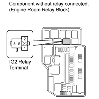
INSPECT IG2 RELAY
-
Remove the IG2 relay from the engine room relay block.
-
Measure the resistance according to the value(s) in the table below.
Standard resistance Tester connection Condition Specified condition 3 - 5 When battery voltage is not applied to terminals 1 and 2 10 kΩ or higher 3 - 5 When battery voltage is applied to terminal 1 and 2 Below 1 Ω
NG
REPLACE IG2 RELAY
OK
-
-
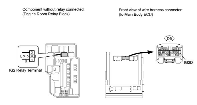
CHECK HARNESS AND CONNECTOR (MAIN BODY ECU - IG2 RELAY)
-
Disconnect the D6 connector from the main body ECU.
-
Measure the resistance according to the value(s) in the table below.
Standard resistance Tester connection Condition Specified condition D6-11 (IG2D) - Engine room relay block IG2 relay terminal 1 Always Below 1 Ω D6-11 (IG2D) or Engine room relay block IG2 relay terminal 1 - Body ground Always 10 kΩ or higher
NG
REPAIR OR REPLACE HARNESS OR CONNECTOR
OK
-
-
CHECK HARNESS AND CONNECTOR (BATTERY - IG2 RELAY)
-
Measure the voltage according to the value(s) in the table below.
Standard voltage Tester connection Condition Specified condition Engine room relay block IG2 relay terminal 5 - Body ground Always 11 to 14 V
NG
REPAIR OR REPLACE HARNESS OR CONNECTOR, OR REPLACE IG2 FUSE
OK
-
-
CHECK HARNESS AND CONNECTOR (IG2 RELAY - BODY GROUND)
-
Measure the resistance according to the value(s) in the table below.
Standard resistance Tester connection Condition Specified condition Engine room relay block IG2 relay terminal 2 - Body ground Always Below 1 Ω
NG
REPAIR OR REPLACE HARNESS OR CONNECTOR
OK
REPLACE MAIN BODY ECU (INSTRUMENT PANEL JUNCTION BLOCK)
-
-
CHECK HARNESS AND CONNECTOR (BATTERY - INSTRUMENT PANEL JUNCTION BLOCK)
-
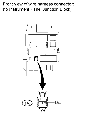
Disconnect the 1A connector from the instrument panel junction block.
-
Measure the voltage according to the value(s) in the table below.
Standard voltage Tester connection Condition Specified condition 1A-1 - Body ground Always 11 to 14 V
NG
REPAIR OR REPLACE HARNESS OR CONNECTOR, OR REPLACE ALT FUSE
OK
-
-
CHECK HARNESS AND CONNECTOR (INSTRUMENT PANEL JUNCTION BLOCK - BODY GROUND)
-
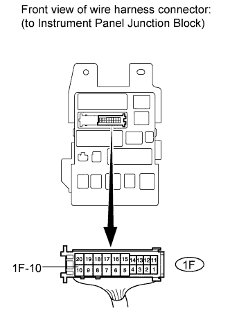
Disconnect the 1F connector from the instrument panel junction block.
-
Measure the resistance according to the value(s) in the table below.
Standard resistance Tester connection Condition Specified condition 1F-10 - Body ground Always Below 1 Ω
NG
REPAIR OR REPLACE HARNESS OR CONNECTOR
OK
REPAIR OR REPLACE HARNESS OR CONNECTOR
-