SMART ENTRY AND START SYSTEM, Diagnostic DTC:B2281
| DTC Code | DTC Name |
|---|---|
| B2281 | "P" Signal Malfunction |
DESCRIPTION
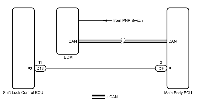
The ECM and the shift lock control ECU are connected by a cable and the CAN. If the cable information and CAN information are inconsistent, this DTC will be output.
Tech Tips
After the main body ECU is replaced, perform the registration procedure for the engine immobiliser system.
| DTC No. | DTC Detection Condition | Trouble Area |
|---|---|---|
| B2281 | Cable information and CAN information between main body ECU and shift lock control ECU are inconsistent |
|
WIRING DIAGRAM
INSPECTION PROCEDURE
PROCEDURE
-
READ VALUE USING INTELLIGENT TESTER
-
Connect the intelligent tester to the DLC3.
-
Turn the engine switch on (IG) and turn the intelligent tester main switch on.
-
Read the DATA LIST according to the displays on the tester.
Body: Tester Display Measurement Item/Range Normal Condition Diagnostic Note SHIFT P SIG Shift P Signal / ON or OFF ON: Shift P signal ON (Shift position is P)
OFF: Shift P signal OFF (Shift position is not P)
- OK "ON" (P signal is ON) and "OFF" (P signal is OFF) appear on the screen.
NG 
GO TO SHIFT CONTROL SYSTEM Click here
OK 
-
-
CHECK WIRE HARNESS (MAIN BODY ECU - SHIFT LOCK CONTROL ECU)
-
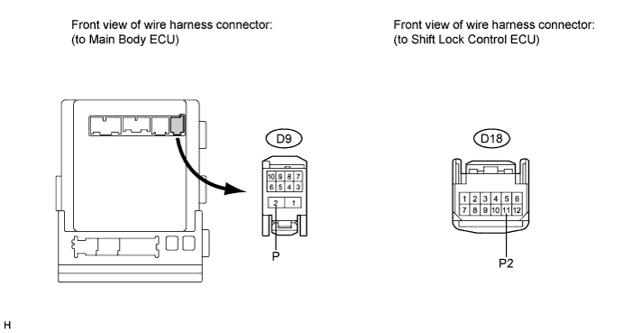
Disconnect the D9 and D18 ECU connectors.
-
Measure the resistance according to the value(s) in the table below.
Standard resistance Terminal No. (Symbol) Condition Specified Condition D9-2 (P) - D18-11 (P2) Always Below 1 Ω D9-2 (P) - Body ground Always 10 kΩ or higher
NG
REPAIR OR REPLACE HARNESS OR CONNECTOR
OK
-
-
CHECK MAIN BODY ECU OPERATION
-
After replacing the main body ECU with a normally functioning one, check that the engine can start normally.
OK Engine can start normally.
NG
REPLACE SHIFT LOCK CONTROL ECU Click here
OK 
END (MAIN BODY ECU DEFECTIVE)
-