SMART ENTRY AND START SYSTEM, Diagnostic DTC:B2275
| DTC Code | DTC Name |
|---|---|
| B2275 | STSW Monitor Malfunction |
DESCRIPTION
This DTC is output if there is an open, short, or any other problem in the engine start request output circuit inside the main body ECU or in the external circuit.
Tech Tips
If the main body ECU is replaced with a new one while the negative (-) battery terminal is connected, the power source mode will be in IG-ON mode. When the battery is removed and reinstalled, the power source mode that was selected when the battery was removed is restored.
After the main body ECU is replaced, perform the registration procedure for the engine immobiliser system.
| DTC No. | DTC Detection Condition | Trouble Area |
|---|---|---|
| B2275 | STSW output circuit (engine starting request signal circuit) inside main body ECU or other related circuit is malfunctioning |
|
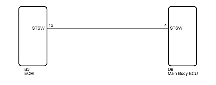
WIRING DIAGRAM
INSPECTION PROCEDURE
PROCEDURE
-
CHECK DTC OUTPUT
-
Delete the DTCs Click here.
Tech Tips
After all DTCs are cleared, turn the engine switch on (IG) and depress the brake pedal. After 15 seconds have elapsed, check if the trouble occurs again.
-
Check for DTCs again.
OK No DTC is output.
NG 
CHECK HARNESS AND CONNECTOR (MAIN BODY ECU - ECM) Click here
OK 
USE SYMPTOM METHOD TO CHECK Click here
-
-
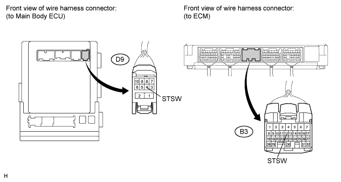
CHECK HARNESS AND CONNECTOR (MAIN BODY ECU - ECM)
-
Disconnect the D9 ECU connector.
-
Disconnect the B3 ECM connector.
-
Measure the resistance according to the value(s) in the table below.
Standard resistance Tester Connection Condition Specified Condition D9-4 (STSW) - B3-12 (STSW) Always Below 1 Ω D9-4 (STSW) - Body ground Always 10 kΩ or higher
NG 
REPAIR OR REPLACE HARNESS OR CONNECTOR
OK 
-
-
INSPECT MAIN BODY ECU
-
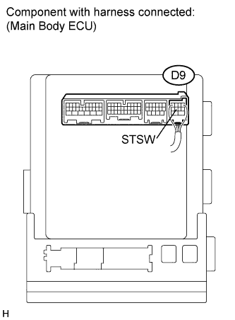
Reconnect the D9 connector.
-
Measure the voltage according to the value(s) in the table below.
Standard voltage Tester Connection Condition Specified Condition D9-4 (STSW) - Body ground Brake pedal depressed, Engine switch hold on (ST) Output voltage at terminal AM1 or AM2 is -2 V or more.
NG
REPLACE MAIN BODY ECU (INSTRUMENT PANEL JUNCTION BLOCK)
OK
REPLACE ECM Click here
-