SMART ENTRY AND START SYSTEM, Diagnostic DTC:B2272
| DTC Code | DTC Name |
|---|---|
| B2272 | Ignition 1 Monitor Malfunction |
DESCRIPTION
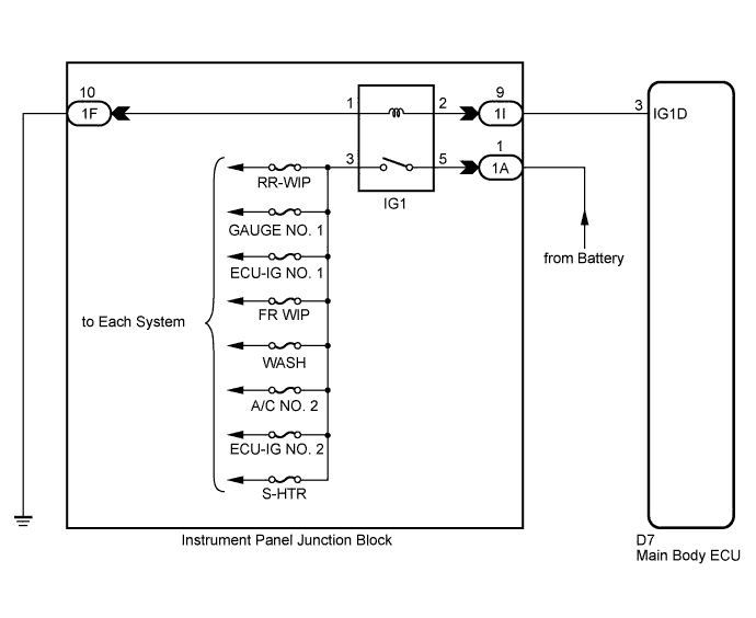
This DTC is output if there is a problem in the IG1D output circuit, which is from the inside of the main body ECU to the IG1 relay.
Tech Tips
If the main body ECU is replaced with a new one while the negative (-) battery terminal is connected, the power source mode will be in IG-ON mode. When the battery is removed and reinstalled, the power source mode that was selected when the battery was removed is restored.
After the main body ECU is replaced, perform the registration procedure for the engine immobiliser system.
| DTC No. | DTC Detection Condition | Trouble Area |
|---|---|---|
| B2272 | IG1 relay actuation circuit inside main body ECU or other related circuit is malfunctioning |
|
WIRING DIAGRAM
INSPECTION PROCEDURE
PROCEDURE
-
READ VALUE USING INTELLIGENT TESTER
-
Connect the intelligent tester to the DLC3.
-
Turn the engine switch on (IG) and turn the intelligent tester main switch on.
-
Select the item below in the Data List, and read the display on the tester.
Tech Tips
When using the intelligent tester with the engine switch off, turn on and off any of the door courtesy light switches repeatedly at 1.5 second intervals or less until communication between the tester and vehicle starts.
Body: Tester Display Measurement Item/Range Normal Condition Diagnostic Note IG1 Relay Mon1 Status of IG1 relay monitor (outer) / ON or OFF ON: Engine switch on (IG) (IG1 relay is ON)
OFF: Engine switch off (IG1 relay is OFF)
- OK "ON" (engine switch on (IG)) appears on the screen.
NG 
INSPECT RELAY (IG1 RELAY) Click here
OK 
-
-
CHECK ENGINE SWITCH CONDITION
-
Check the power source mode change.
-
When the key is inside the vehicle and the shift lever is in the P position, check that pressing the engine switch causes the power source mode to change as follows:
OK off → on (ACC) → on (IG) → off
-
NG 
GO TO OTHER FLOW CHART Click here
OK
-
-
CHECK DTC OUTPUT
-
Delete the DTCs Click here.
-
Check for DTCs again.
OK No DTC is output.
NG
REPLACE MAIN BODY ECU (INSTRUMENT PANEL JUNCTION BLOCK)
OK 
USE SYMPTOM METHOD TO CHECK Click here
-
-
INSPECT RELAY (IG1 RELAY)
-
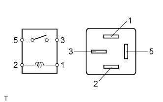
Remove the IG1 relay from the instrument panel junction block.
-
Measure the resistance according to the value(s) in the table below.
Standard resistance Tester Connection Condition Specified Condition 3 - 5 When battery voltage is not applied to terminals 1 and 2 10 kΩ or higher 3 - 5 When battery voltage is applied to terminals 1 and 2 Below 1 Ω
NG
REPLACE IG1 RELAY
OK
-
-
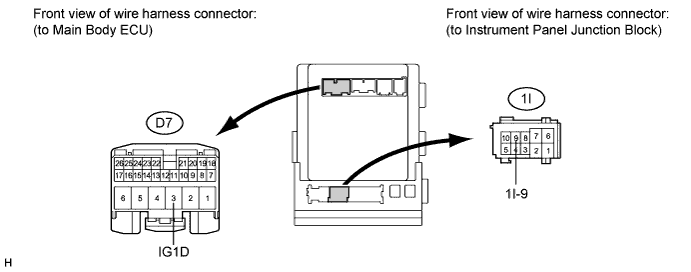
CHECK HARNESS AND CONNECTOR (INSTRUMENT PANEL JUNCTION BLOCK - MAIN BODY ECU)
-
Disconnect the 1I junction block connector.
-
Disconnect the D7 ECU connector.
-
Measure the resistance according to the value(s) in the table below.
Standard resistance Tester Connection Condition Specified Condition 1I-9 - D7-3 (IG1D) Always Below 1 Ω D7-3 (IG1D) - Body ground Always 10 kΩ or higher
NG
REPAIR OR REPLACE HARNESS OR CONNECTOR (INSTRUMENT PANEL JUNCTION BLOCK - MAIN BODY ECU)
OK
-
-
CHECK HARNESS AND CONNECTOR (INSTRUMENT PANEL JUNCTION BLOCK - BATTERY AND BODY GROUND)
-
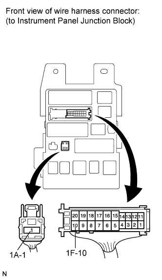
Disconnect the 1F and 1A junction block connectors.
-
Measure the resistance according to the value(s) in the table below.
Standard resistance Tester Connection Condition Specified Condition 1F-10 - Body ground Always Below 1 Ω -
Measure the voltage according to the value(s) in the table below.
Standard voltage Tester Connection Condition Specified Condition 1A-1 - Body ground Always 11 to 14 V
NG
REPAIR OR REPLACE HARNESS OR CONNECTOR (INSTRUMENT PANEL JUNCTION BLOCK - BATTERY AND BODY GROUND)
OK
REPLACE MAIN BODY ECU (INSTRUMENT PANEL JUNCTION BLOCK)
-