SMART ENTRY AND START SYSTEM, Diagnostic DTC:B2271
| DTC Code | DTC Name |
|---|---|
| B2271 | Ignition Hold Monitor Malfunction |
DESCRIPTION
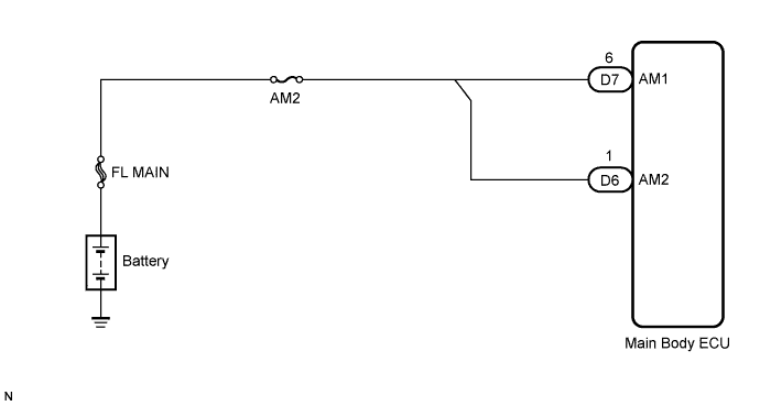
This DTC is output if a problem such as an open in the AM2 fuse, an open or short in the wire harness between the fuse and main body ECU, a short in the IG output circuit inside the main body ECU, a short between the main body ECU and relay, and a short in the relay is detected.
Tech Tips
If the main body ECU is replaced with a new one while the negative (-) battery terminal is connected, the power source mode will be in IG-ON mode. When the battery is removed and reinstalled, the power source mode that was selected when the battery was removed is restored.
After the main body ECU is replaced, perform the registration procedure for the engine immobiliser system.
| DTC No. | DTC Detection Condition | Trouble Area |
|---|---|---|
| B2271 | Hold circuit, IG1 relay actuation circuit or IG2 relay actuation circuit inside main body ECU is open or shorted |
|
WIRING DIAGRAM
INSPECTION PROCEDURE
PROCEDURE
-
CHECK DTC OUTPUT
-
Delete the DTCs Click here.
Tech Tips
After all DTCs are cleared, check if the trouble occurs again 6 seconds after the engine switch is turned on (IG).
-
Check for DTCs again.
OK No DTC is output.
NG 
CHECK HARNESS AND CONNECTOR (MAIN BODY ECU - BATTERY) Click here
OK 
USE SYMPTOM METHOD TO CHECK Click here
-
-
CHECK HARNESS AND CONNECTOR (MAIN BODY ECU - BATTERY)
-
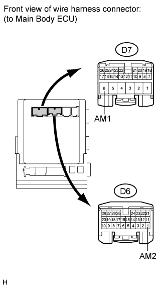
Disconnect the D6 and D7 ECU connectors.
-
Measure the voltage according to the value(s) in the table below.
Standard voltage Tester Connection Condition Specified Condition D7-6 (AM1) - Body ground Always 11 to 14 V D6-1 (AM2) - Body ground Always 11 to 14 V
NG 
REPAIR OR REPLACE HARNESS OR CONNECTOR, OR FUSE
OK
REPLACE MAIN BODY ECU (INSTRUMENT PANEL JUNCTION BLOCK)
-