| DTC Code | DTC Name |
|---|---|
| B2285 | Steering Lock Position Signal Circuit Malfunction |
DESCRIPTION
This DTC is output if serial communication signals and LIN communication signals in the circuit between the main body ECU and steering lock actuator (steering lock ECU) are inconsistent.
If the main body ECU is replaced with a new one while the negative (-) battery terminal is connected, the power source mode will be in IG-ON mode. When the battery is removed and reinstalled, the power source mode that was selected when the battery was removed is restored.
After the main body ECU or steering lock ECU is replaced, perform the registration procedure for the engine immobiliser system.
| DTC No. | DTC Detection Condition | Trouble Area |
|---|---|---|
| B2285 | Cable and LIN information between the main body ECU and the steering lock ECU are inconsistent |
|
INSPECTION PROCEDURE
PROCEDURE
- Click here
READ VALUE USING INTELLIGENT TESTER
-
Connect the intelligent tester to the DLC3.
-
Check the DATA LIST for proper functioning of the steering lock function.
Tip:When using the intelligent tester with the engine switch off, turn on and off any of the door courtesy light switches repeatedly at 1.5 second intervals or less until communication between the tester and vehicle starts.
Table 1. Body: Tester Display Measurement Item/Range Normal Condition Diagnostic Note Str Unlock SW Steering lock condition / ON or OFF ON: Steering is unlocked (Engine switch on (ACC))
OFF: Steering is locked (Engine switch off)
- OK ON (steering is unlocked) and OFF (steering is locked) appear on the screen.
- OKClick here
- NGClick here
-
- Click here
CHECK FOR DTCS
-
Delete the DTCs (Click here).
-
Check for DTC B2285 (Steering lock position signal circuit malfunction), DTC B2287 (LIN communication master malfunction) and DTC B2785 (Communication malfunction between ECUs connected by LIN).
Result Result Proceed to Only "DTC B2285" is output A "DTC B2287" and/or "DTC B2785" is output B No DTC is output C Tip:If DTC B2287 is output, perform troubleshooting for DTC B2287 first.
-
- Click here
CHECK HARNESS AND CONNECTOR (MAIN BODY ECU - STEERING LOCK ECU)
-
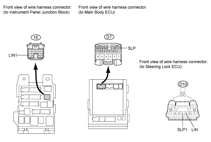
Disconnect the D7, 1E and D10 connectors.
-
Measure the resistance according to the value(s) in the table below.
Standard resistance Tester Connection Condition Specified Condition D7-18 (SLP) - D10-4 (SLP1) Always Below 1 Ω 1E-7 (LIN1) - D10-5 (LIN) Always Below 1 Ω D7-18 (SLP) or D10-4 (SLP1) - Body ground Always 10 kΩ or higher 1E-7 (LIN1) or D10-5 (LIN) - Body ground Always 10 kΩ or higher
- OKClick here
- NGClick here
-
- Click here
CHECK MAIN BODY ECU OPERATION
-
After replacing the main body ECU with a normally functioning one, check that the engine starts. Make sure the brake pedal is depressed and the shift lever is in the P position at this time.
-
Check that the engine switch mode can be changed by pushing the engine switch.
Tip:Without depressing the brake pedal, push the engine switch repeatedly. Engine switch mode should turn from off to on (ACC) to on (IG) and back to off. With the brake pedal depressed, push the engine switch. Engine switch mode should turn to ENGINE START from any status.
OK Engine starts normally.
- OKClick here
- NGClick here
-
- Click here
END (MAIN BODY ECU DEFECTIVE)
- Click here
REPLACE MAIN BODY ECU (INSTRUMENT PANEL JUNCTION BLOCK)
- Click here
GO TO DTC CHARTClick here
- Click here
USE SYMPTOM METHOD TO CHECKClick here
- Click here
REPAIR OR REPLACE HARNESS OR CONNECTOR
- Click here
REPLACE STEERING LOCK ECUClick here