SMART ENTRY AND START SYSTEM, Diagnostic DTC:B2284
| DTC Code | DTC Name |
|---|---|
| B2284 | Brake Signal Malfunction |
DESCRIPTION
Tech Tips
If the main body ECU is replaced with a new one while the negative (-) battery terminal is connected, the power source mode will be in IG-ON mode. When the battery is removed and reinstalled, the power source mode that was selected when the battery was removed is restored.
After the main body ECU is replaced, perform the registration procedure for the engine immobiliser system.
| DTC No. | DTC Detection Condition | Trouble Area |
|---|---|---|
| B2284 | The brake signal circuit between the main body ECU and the stop light switch is malfunctioning and the CAN information is inconsistent |
|
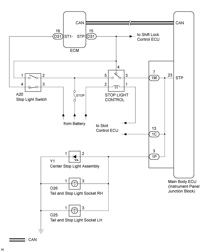
WIRING DIAGRAM
INSPECTION PROCEDURE
-
EMERGENCY ENGINE START CONTROL
-
If there is a malfunction in the stop light switch circuit or STOP fuse, their signals may not be correctly transmitted to the main body ECU. This may result in the engine not starting even if the engine switch is pressed while the brake pedal is depressed and the shift lever is in the P position.
To activate the starter:
-
Turn the engine switch from off to on (ACC).
-
Press and hold the engine switch for 15 seconds.
-
-
PROCEDURE
-
CHECK DTC OUTPUT (CAN COMMUNICATION SYSTEM)
-
Delete the DTCs Click here.
-
Check for CAN communication system DTCs Click here.
Tech Tips
If the DTCs for the CAN communication system malfunction are output, inspect those DTCs first Click here.
OK DTCs for CAN communication system are not output.
NG 
GO TO CAN COMMUNICATION SYSTEM Click here
OK 
-
-
CHECK DTC OUTPUT
-
Delete the DTCs Click here.
-
Check for DTCs again.
-
Proceed to the next step based on the inspection result.
Result Result Proceed to No DTC is output A Engine control system DTCs are output B Vehicle stability control system DTCs are output C
B
GO TO ENGINE CONTROL SYSTEM Click here
C
GO TO VEHICLE STABILITY CONTROL SYSTEM Click here
A
-
-
READ VALUE USING INTELLIGENT TESTER (STOP LIGHT SWITCH)
-
Connect the intelligent tester to the DLC3.
-
Turn the engine switch on (IG).
-
Check the DATA LIST for proper functioning of the stop light switch.
Body: Tester Display Measurement Item/Range Normal Condition Diagnostic Note Stop Light SW Stop light switch/ON or OFF ON: Brake pedal depressed
OFF: Brake pedal released
- OK ON (brake pedal depressed) and OFF (brake pedal released) appear on the screen.
NG 
CHECK OPERATION OF STOP LIGHT Click here
OK 
REPLACE MAIN BODY ECU (INSTRUMENT PANEL JUNCTION BLOCK)
-
-
CHECK OPERATION OF STOP LIGHT
-
Check whether the stop lights turn on and off normally when the brake pedal is depressed and released.
OK Stop lights turn on when brake pedal is depressed.
NG
CHECK HARNESS AND CONNECTOR (STOP LIGHT CONTROL RELAY - INSTRUMENT PANEL JUNCTION BLOCK) Click here
OK
REPLACE MAIN BODY ECU (INSTRUMENT PANEL JUNCTION BLOCK
-
-
CHECK HARNESS AND CONNECTOR (STOP LIGHT CONTROL RELAY - INSTRUMENT PANEL JUNCTION BLOCK)
-
Disconnect the 1M connector from the instrument panel junction block.
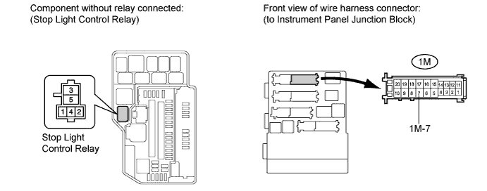
-
Remove the stop light control relay from the engine room relay block.
-
Measure the resistance according to the value(s) in the table below.
Standard resistance Tester Connection Condition Specified Condition 1M-7 - Engine room relay block stop light control relay terminal 3 Always Below 1 Ω 1M-7 - Body ground Always 10 kΩ or higher
NG
REPAIR OR REPLACE HARNESS OR CONNECTOR
OK
REPLACE MAIN BODY ECU (INSTRUMENT PANEL JUNCTION BLOCK
-