ENGINE OIL COOLER REMOVAL
-
REMOVE BATTERY
-
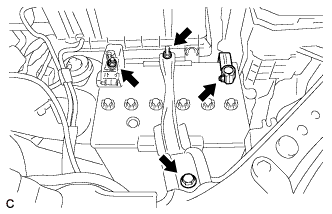
Loosen the nut, and disconnect the negative battery terminal.
CAUTION:
Wait for 90 seconds after disconnecting the cable to prevent the airbag working.
Note
When disconnecting the cable, some systems need to be initialized after the cable is reconnected Click here.
-
Remove the nut, and separate the positive battery terminal cable.
-
Loosen the nut, and remove the bolt and battery clamp.
-
Remove the battery and battery tray.
-
-
REMOVE COOL AIR INTAKE DUCT SEAL
-
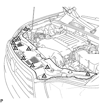
Remove the 11 clips and cool air intake duct seal.
-
-
REMOVE NO. 2 AIR CLEANER INLET
-
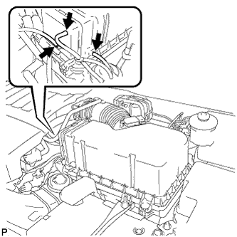
Disconnect the 2 vacuum switching valve clamps.
-
Disconnect the 2 vacuum hoses.
-
Remove the 2 bolts and No. 2 air cleaner inlet.
-
-
REMOVE NO. 1 AIR CLEANER INLET
-
Disconnect the 2 vacuum hoses, and remove the 2 bolts and No. 1 air cleaner inlet.
-
-
REMOVE AIR CLEANER CAP SUB-ASSEMBLY
-
Disconnect the 3 vacuum hoses.
-
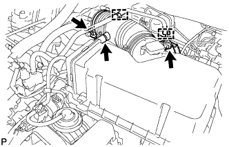
Loosen the No. 1 air cleaner hose clamp.
-
Disconnect the hose clamps and No. 2 ventilation hose.
-
Disconnect the mass air flow meter connector.
-
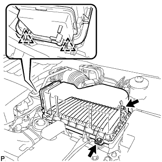
Release the 2 clips, and remove the 2 bolts.
-
Remove the air cleaner cap sub-assembly and air cleaner filter element.
-
-
REMOVE AIR CLEANER CASE SUB-ASSEMBLY
-
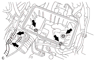
Remove the 3 bolts, disconnect the hose and the connector, and remove the air cleaner case sub-assembly.
-
-
REMOVE V-BANK COVER SUB-ASSEMBLY
-
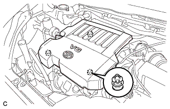
Hold the front of the V-bank cover sub-assembly and raise it to disengage the 2 clips on the front of the V-bank cover sub-assembly. Continue rising the V-bank cover sub-assembly to disengage the clip on the rear of the V-bank cover sub-assembly and remove the V-bank cover sub-assembly.
Note
Attempting to disengage both front and rear clips at the same time may cause the V-bank cover sub-assembly to break.
-
-
REMOVE ENGINE UNDER COVER ASSEMBLY
-

Remove the 2 bolts and engine under cover assembly RR.
-

Remove the 2 bolts, 2 screws, 5 clips and engine under cover assembly.
-
-
REMOVE NO. 1 ENGINE UNDER COVER
-
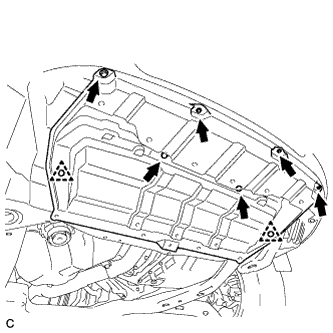
Remove the 6 bolts, 2 clips and No. 1 engine under cover.
-
-
REMOVE NO. 2 ENGINE UNDER COVER
-
Remove the 2 bolts and No. 2 engine under cover.
-
-
DRAIN ENGINE COOLANT
-
Loosen the radiator drain cock plug.
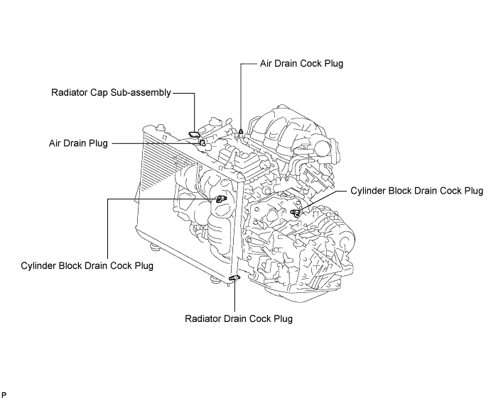
Tech Tips
Collect the coolant in a container and dispose of it according to the regulations in your area.
-
Remove the radiator cap sub-assembly from the radiator assembly.
Note
Do not remove the radiator cap sub-assembly while the engine and radiator are still hot. Pressurized, hot engine coolant and steam may be released and cause serious burns.
-
Loosen the 2 cylinder block drain cock plugs.
-
-
DRAIN ENGINE OIL
-
Remove the oil filler cap.
-
Remove the oil drain plug and drain the oil into a container.
-
Clean the oil drain plug.
-
Install the oil drain plug with a new gasket.
- Torque:
- 40 N*m { 408 kgf*cm, 30 ft.*lbf }
-
-
DISCONNECT NO. 1 RADIATOR HOSE
-
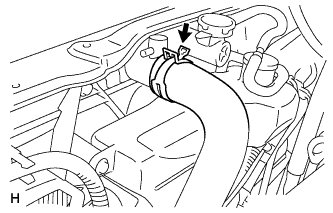
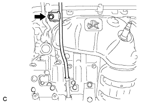
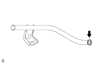
Disconnect the No. 1 radiator hose from the radiator.
-
-
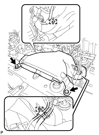
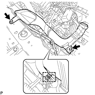
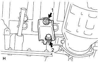
REMOVE RADIATOR RESERVE TANK ASSEMBLY
-
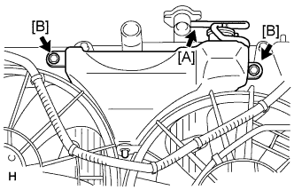
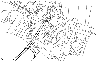
Disconnect the hose [A].
-
Remove the 2 bolts [B] and radiator reserve tank assembly.
-
-
REMOVE NO. 2 ENGINE OIL LEVEL DIPSTICK GUIDE
-
Remove the oil level dipstick.
-
Remove the bolt and No. 2 engine oil level dipstick guide.
-
Remove the O-rings from the No. 2 engine oil level dipstick guide.
-
-
REMOVE NO. 2 EXHAUST MANIFOLD HEAT INSULATOR
-
Disconnect the air fuel ratio sensor connector and remove the clamp.
-
Remove the 3 bolts and No. 2 exhaust manifold heat insulator.
-
-
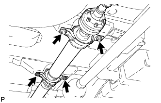
REMOVE PROPELLER SHAFT ASSEMBLY (for 4WD)
-
Depress the brake pedal and hold it.
-
Using a hexagon wrench (6 mm), loosen the cross groove joint set bolts 1/2 turn.
Tech Tips
Put a piece of cloth or equivalent into the inside of the universal joint cover so that the boot does not touch the inside of the universal joint cover.
-
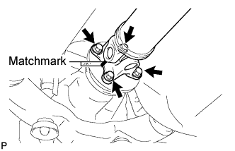
Place matchmarks on the rear propeller shaft and rear drive pinion flange sub-assembly.
-
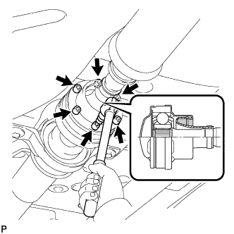
Remove the 4 nuts, 4 bolts and 4 washers.
-
Remove the 4 bolts and 4 adjusting shims.
-
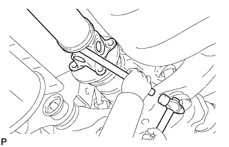
Using a brass bar and a hammer, remove the propeller shaft with center bearing shaft assembly.
-
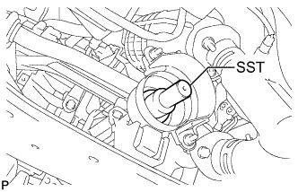
Insert SST into the transfer to prevent oil leakage.
- SST
- 09325-20010
-
-
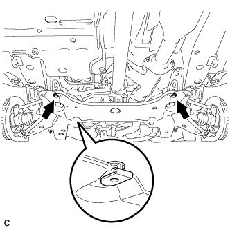
REMOVE TAIL EXHAUST PIPE ASSEMBLY
-
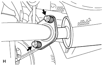
Remove the 2 bolts and 2 compression springs.
-
Disconnect the exhaust pipe support and remove the tail exhaust pipe assembly.
-
Remove the gasket from the center exhaust pipe assembly.
-
-
REMOVE CENTER EXHAUST PIPE ASSEMBLY
-
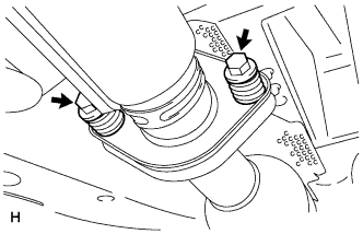
Remove the 2 bolts and 2 compression springs.
-
Disconnect the 3 exhaust pipe supports and remove the center exhaust pipe assembly.
-
Remove the gasket from the No. 3 exhaust pipe sub-assembly.
-
-
REMOVE FRONT NO. 3 EXHAUST PIPE SUB-ASSEMBLY
-
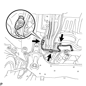
Remove the 3 clamps and disconnect the heated oxygen sensor (for bank 1 sensor 2) connector.
-
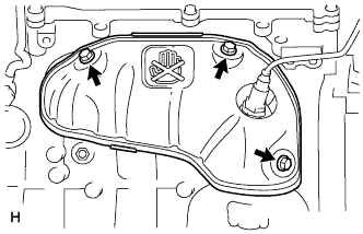
Remove the 2 bolts, 2 nuts and front No. 3 exhaust pipe sub-assembly.
-
Remove the 2 gaskets from the front No. 3 exhaust pipe sub-assembly.
-
-
REMOVE FRONT EXHAUST PIPE ASSEMBLY
-
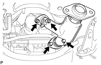
Disconnect the heated oxygen sensor (for bank 2 sensor 2) connector.
-
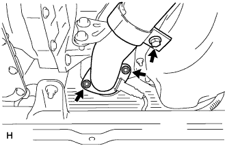
Loosen the bolt.
-
Remove the 2 nuts and front exhaust pipe assembly.
-
Remove the gasket from the front exhaust pipe assembly.
-
-
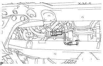
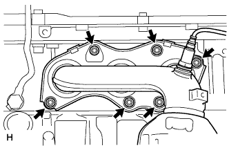
REMOVE NO. 2 MANIFOLD STAY
-
Install the No. 2 manifold stay by tightening the bolt and nut in the order shown in the illustration.
- Torque:
- 34 N*m { 347 kgf*cm, 25 ft.*lbf }
-
-
REMOVE EXHAUST MANIFOLD ASSEMBLY LH
-
Remove the 6 nuts and exhaust manifold assembly LH.
-
Remove the gasket.
-
-
REMOVE ENGINE OIL COOLER
-
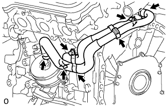
Remove the bolt, 2 clamps, and 4 clips, and disconnect the 2 water by-pass hoses.
-
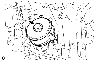
Remove the oil cooler union bolt, oil cooler assembly, and O-ring.
-