- Click here
INSTALL WATER PUMP ASSEMBLY
-
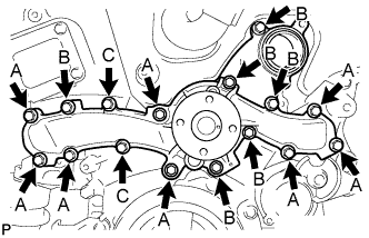
Install a new water pump gasket and the water pump assembly with the 16 bolts.
Bolt A 21 N*m 214 kgf*cm 16 ft.*lbf Bolts B and C 9.1 N*m 93 kgf*cm 81 in.*lbf Note:
-
Make sure that there is no oil on the threads of bolts A.
-
Be sure to replace 2 bolts C with new ones or reuse them after applying adhesive 1344.
Adhesive Toyota Genuine Adhesive 1344, Three Bond 1344 or equivalent
-
-
- Click here
INSTALL WATER INLET HOUSING
-
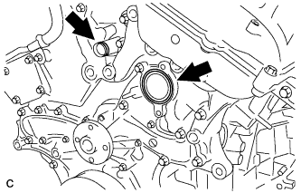
Install a new water inlet housing gasket and water outlet pipe O-ring.
-
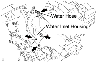
Install the water inlet housing with the 2 bolts and nut.
10 N*m 102 kgf*cm 7 ft.*lbf Note:Be careful not to allow the O-ring to get caught between the parts.
-
Connect the water hose.
-
- Click here
INSTALL WATER PUMP PULLEY
-
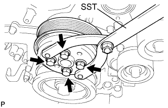
Temporarily install the water pump pulley with the 4 bolts.
-
Using SST, hold the water pump pulley.
09960-10010 09962-01000 09963-00700 -
Tighten the 4 bolts.
21 N*m 214 kgf*cm 16 ft.*lbf
-
- Click here
INSTALL V-RIBBED BELT TENSIONER ASSEMBLY
-
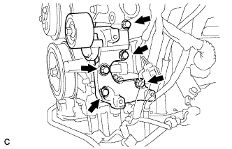
Install the V-ribbed belt tensioner assembly with the 5 bolts.
43 N*m 438 kgf*cm 32 ft.*lbf
-
- Click here
INSTALL NO. 2 IDLER PULLEY SUB-ASSEMBLY
-
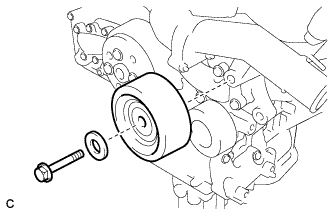
Install the idler pulley cover plate and idler pulley sub-assembly with the bolt.
43 N*m 438 kgf*cm 32 ft.*lbf
-
- Click here
INSTALL GENERATOR ASSEMBLY
-
Install the wire harness clamp bracket with the bolt.
20 N*m 204 kgf*cm 15 ft.*lbf -
Connect the generator bracket with the wire harness clamp.
-
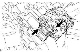
Install generator assembly with the 2 bolts.
43 N*m 438 kgf*cm 32 ft.*lbf -
Temporarily install the 2 bolts.
-
Fully tighten the 2bolts.
20 N*m 204 kgf*cm 15 ft.*lbf -
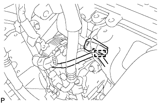
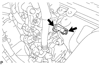
Connect the generator connector to the generator assembly.
-
Install the generator wire with the nut.
9.8 N*m 100 kgf*cm 87 in.*lbf -
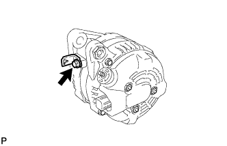
Install the terminal cap.
-
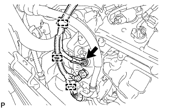
Connect the 3 wire harness clamps.
-
Connect the magnetic clutch connector to the compressor and magnetic clutch.
-
- Click here
INSTALL ENGINE HANGERS
-
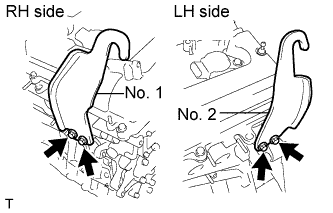
Install the 2 engine hangers with the 4 bolts as shown in the illustration.
Part No. No. 1 Engine hanger 12281-31120 No. 2 Engine hanger 12282-31100 Bolts 91671-10825 33 N*m 337 kgf*cm 24 ft.*lbf -
Attach the engine sling device and hang the engine with the chain block.
-
- Click here
REMOVE ENGINE STAND
- Click here
INSTALL ENGINE ASSEMBLY WITH TRANSAXLE
Tip: