WATER PUMP ON-VEHICLE INSPECTION
-
REMOVE FRONT WHEEL RH
-
REMOVE ENGINE UNDER COVER ASSEMBLY
-

Remove the 2 bolts and engine under cover assembly RR.
-

Remove the 2 bolts, 2 screws, 5 clips and engine under cover assembly.
-
-
REMOVE NO. 1 ENGINE UNDER COVER
-
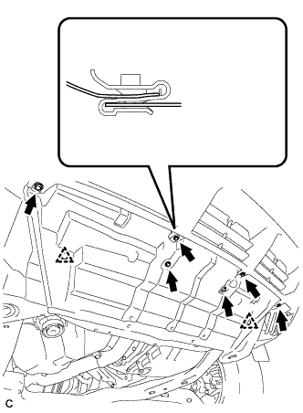
Remove the 6 bolts, 2 clips and No. 1 engine under cover.
-
-
REMOVE FRONT FENDER MOULDING SUB-ASSEMBLY RH
Tech Tips
Use the same procedures for the RH side and LH side Click here.
-
REMOVE FRONT FENDER LINER RH
-
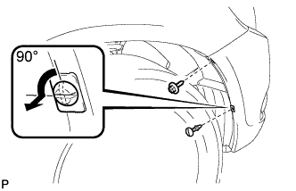
Remove the screw.
-
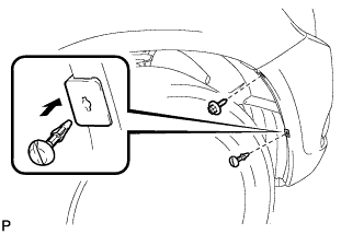
Using a screwdriver, turn the pin 90 degrees and remove the pin hold clip.
-
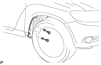
Using a 4 mm hexagon wrench, remove the 2 screws.
-
Remove the 2 grommets.
Tech Tips
The grommets need to be replaced with new ones because they will break when they are removed.
-
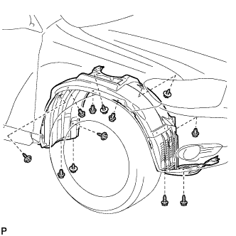
Remove the 5 clips, 7 screws and front fender liner RH.
-
-
REMOVE FRONT FENDER APRON SEAL RH
-
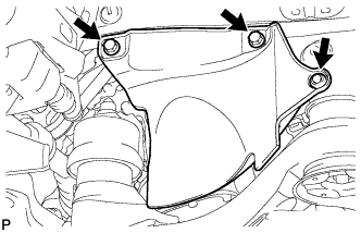
Remove the 2 bolts, clip and front fender apron seal RH.
-
-
REMOVE V-RIBBED BELT
-
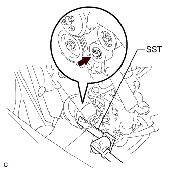
Using SST, release the V-ribbed belt tension by turning the V-ribbed belt tensioner assembly counterclockwise, and remove the V-ribbed belt from the V-ribbed belt tensioner assembly.
- SST
- 09961-00950
-
While turning the V-ribbed belt tensioner assembly counterclockwise, align with its holes, and then insert the 5 mm bi-hexagon wrench into the holes to fix the V-ribbed belt tensioner assembly.
-
-
INSPECT WATER PUMP ASSEMBLY
-
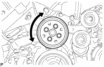
Turn the pulley and check that the water pump bearing moves smoothly and quietly.
If necessary, replace the water pump assembly.
-
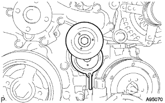
Make sure that there are no drops of coolant on the water pump housing.
If necessary, replace the water pump assembly.
-
-
INSTALL V-RIBBED BELT
-
Install the V-ribbed belt.
-
Using SST, turn the V-ribbed belt tensioner assembly counterclockwise and remove the bar.
- SST
- 09961-00950
-
If it is difficult to install the V-ribbed belt, perform the following procedure:
-
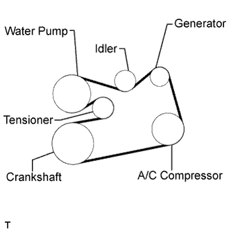
Put the V-ribbed belt on every pulley except the tensioner pulley as shown in the illustration.
-
Release the V-ribbed belt tension by turning the V-ribbed belt tensioner assembly counterclockwise, and put the V-ribbed belt on the V-ribbed belt tensioner assembly pulley.
Note
-
Put the backside of the V-ribbed belt on the V-ribbed belt tensioner assembly pulley and No. 2 idler pulley sub-assembly.
-
Check that the V-ribbed belt is properly set to each pulley.
-
-
After installing the V-ribbed belt, check that it fits properly in the ribbed grooves. Confirm that the V-ribbed belt has not slipped out of the grooves on the bottom of the crankshaft pulley by hand.
-
-
-
INSTALL FRONT FENDER APRON SEAL RH
-
Install the front fender apron seal RH with the 2 bolts and clip.
-
-
INSTALL FRONT FENDER LINER RH
-
Install the front fender liner RH with the 5 clips and 7 screws.
-
Install 2 new grommets.
-
Using a 4 mm hexagon wrench, install the 2 screws.
-
Install the screw and pin hold clip.
- Torque:
- 3.0 N*m { 31 kgf*cm, 27 in.*lbf }
-
-
INSTALL FRONT FENDER MOULDING SUB-ASSEMBLY RH
Tech Tips
Use the same procedures for the RH side and LH side Click here.
-
INSTALL NO. 1 ENGINE UNDER COVER
-
Install the No. 1 engine under cover with the 6 bolts and 2 clips.
-
-
INSTALL ENGINE UNDER COVER ASSEMBLY
-
Install the engine under cover assembly with the 2 bolts, 2 screws and 5 clips.
-
Install the engine under cover assembly RR with the 2 bolts.
-
-
INSTALL FRONT WHEEL RH
- Torque:
- 103 N*m { 1050 kgf*cm, 76 ft.*lbf }