EXHAUST PIPE INSTALLATION
-
INSTALL HEATED OXYGEN SENSOR (for Bank 2 Sensor 2)
-
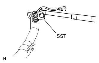
Using SST, install the heated oxygen sensor to the front exhaust pipe assembly.
- SST
- 09224-00010
- Torque:
- 40 N*m { 408 kgf*cm, 30 ft.*lbf, for use with SST }
- 44 N*m { 449 kgf*cm, 32 ft.*lbf, for use without SST }
Tech Tips
-
Use a torque wrench with a fulcrum length of 30 cm (11.81 in.).
-
Make sure that SST and the wrench are connected in a straight line.
-
-
INSTALL FRONT EXHAUST PIPE ASSEMBLY
-
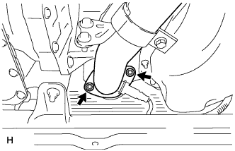
Install a new gasket to the front exhaust pipe assembly.
-
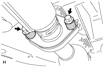
Install the front exhaust pipe assembly with 2 new nuts.
- Torque:
- 56 N*m { 571 kgf*cm, 41 ft.*lbf }
-
Connect the heated oxygen sensor (for bank 2 sensor 2) connector.
-
-
INSTALL HEATED OXYGEN SENSOR (for Bank 1 Sensor 2)
-
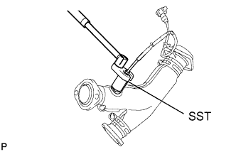
Using SST, install the heated oxygen sensor to the front No. 3 exhaust pipe sub-assembly.
- SST
- 09224-00010
- Torque:
- 40 N*m { 408 kgf*cm, 30 ft.*lbf, for use with SST }
- 44 N*m { 449 kgf*cm, 32 ft.*lbf, for use without SST }
Tech Tips
-
Use a torque wrench with a fulcrum length of 30 cm (11.81 in.).
-
Make sure that SST and the wrench are connected in a straight line.
-
-
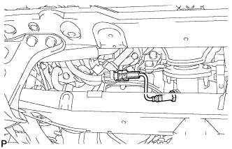
INSTALL FRONT NO. 3 EXHAUST PIPE SUB-ASSEMBLY
-
Install 2 new gaskets to the front No. 3 exhaust pipe sub-assembly.
-
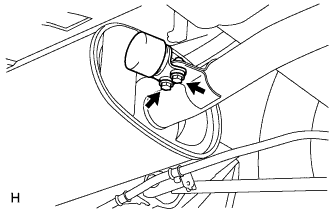
Install the front No. 3 exhaust pipe sub-assembly with 2 new nuts and the 2 bolts.
- Torque:
- 56 N*m { 571 kgf*cm, 41 ft.*lbf }
-
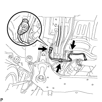
Install the 3 clamps and connect the heated oxygen sensor (for bank 1 sensor 2) connector.
-
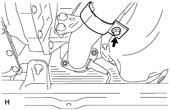
Tighten the front exhaust pipe assembly bolt.
- Torque:
- 21 N*m { 214 kgf*cm, 15 ft.*lbf }
-
-
INSTALL CENTER EXHAUST PIPE ASSEMBLY
-
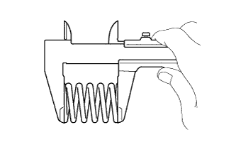
Using vernier calipers, measure the free length of the compression spring.
Minimum 41.5 mm (1.63 in.) Tech Tips
If the length is less than the minimum, replace the compression spring.
-
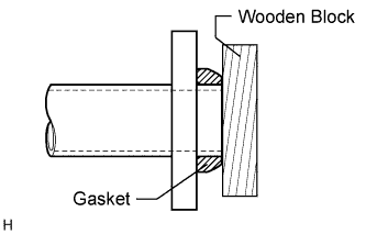
Using a plastic-faced hammer and wooden block, tap in a new gasket until its surface is flush with the front No. 3 exhaust pipe sub-assembly.
Note
-
Tap in the gasket in the correct direction.
-
Do not reuse the removed gasket.
-
Do not push in the gasket while installing the center exhaust pipe assembly.
-
-
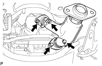
Connect the 3 exhaust pipe supports, and install the center exhaust pipe assembly.
-
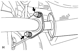
Install the 2 compression springs and 2 bolts.
- Torque:
- 48 N*m { 489 kgf*cm, 35 ft.*lbf }
-
-
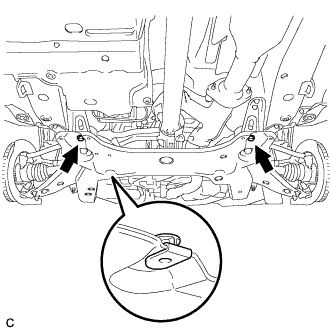
INSTALL EXHAUST PIPE DAMPER
-
Install the exhaust pipe damper with the 2 bolts.
- Torque:
- 19 N*m { 194 kgf*cm, 14 ft.*lbf }
-
-
INSTALL TAIL EXHAUST PIPE ASSEMBLY
-
Using vernier calipers, measure the free length of the compression spring.
Minimum 40.5 mm (1.59 in.) Tech Tips
If the length is less than the minimum, replace the compression spring.
-
Using a plastic-faced hammer and wooden block, tap in a new gasket until its surface is flush with the center exhaust pipe assembly.
Note
-
Tap in the gasket in the correct direction.
-
Do not reuse the removed gasket.
-
Do not push in the gasket while installing the tail exhaust pipe assembly.
-
-
Connect the exhaust pipe support, and install the tail exhaust pipe assembly.
-
Install the 2 compression springs and 2 bolts.
- Torque:
- 48 N*m { 489 kgf*cm, 35 ft.*lbf }
-
-
INSPECT FOR EXHAUST GAS LEAK
If exhaust gas is leaking, repair the leak. Replace damaged or worn parts as necessary.
-
INSTALL NO. 2 ENGINE UNDER COVER
-
Install the No. 2 engine under cover with the 2 bolts.
-
-
INSTALL NO. 1 ENGINE UNDER COVER
-
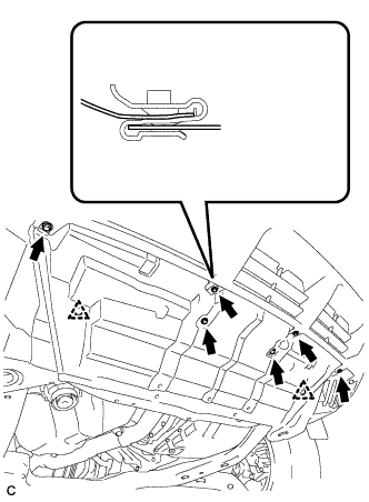
Install the No. 1 engine under cover with the 6 bolts and 2 clips.
-
-
INSTALL ENGINE UNDER COVER ASSEMBLY
-

Install the engine under cover assembly with the 2 bolts, 2 screws and 5 clips.
-

Install the engine under cover assembly RR with the 2 bolts.
-