- Click here
DISCHARGE FUEL SYSTEM PRESSURE
Tip: - Click here
DISCONNECT CABLE FROM NEGATIVE BATTERY TERMINAL
Note:When disconnecting the cable, some systems need to be initialized after the cable is reconnected (Click here).
- Click here
REMOVE REAR CENTER SEAT ASSEMBLY
- Click here
REMOVE REAR SEAT HEADREST ASSEMBLY (for LH Side)
- Click here
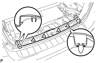
REMOVE SEAT TRACK BRACKET COVER LH
-
Disengage the 8 claws and remove the 2 rear seat track bracket covers.
-
- Click here
REMOVE REAR OUTER TRACK BRACKET COVER LH
-
Disengage the 4 claws and remove the rear outer track bracket cover.
-
- Click here
REMOVE REAR INNER TRACK BRACKET COVER LH
-
Disengage the 4 claws and remove the rear inner track bracket cover.
-
- Click here
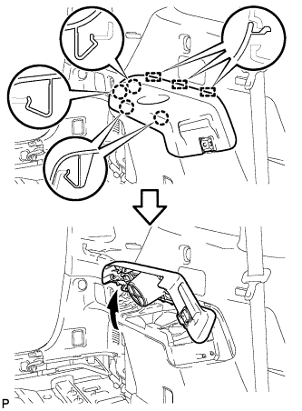
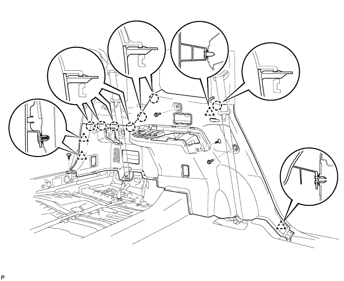
REMOVE REAR SEAT LEG SIDE COVER LH
-
Disengage the 3 claws.
-
Disengage the clip and remove the rear seat leg side cover.
-
- Click here
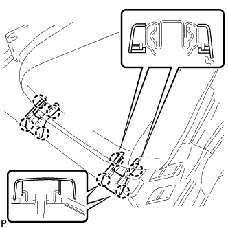
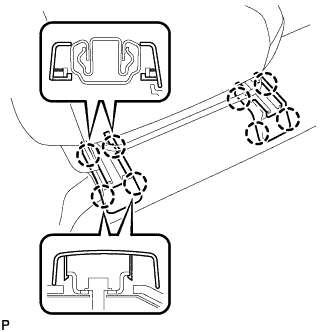
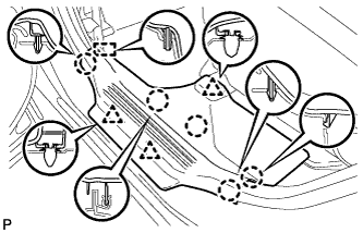
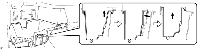
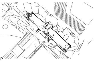
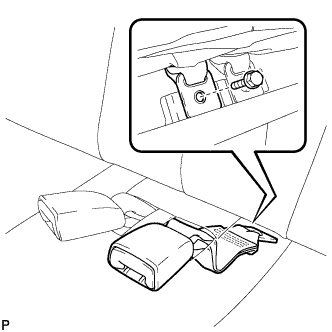
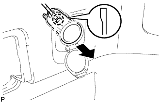
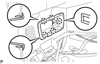
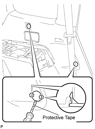
DISCONNECT REAR NO. 1 SEAT LOCK CABLE ASSEMBLY LH (w/ Remote Folding Function)
-
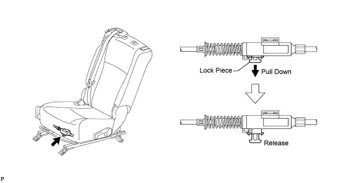
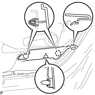
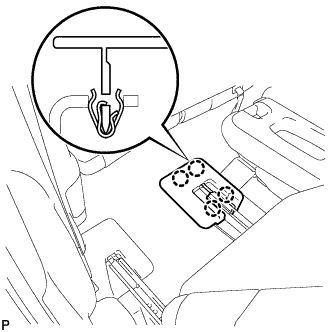
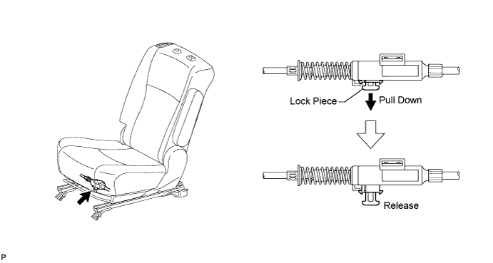
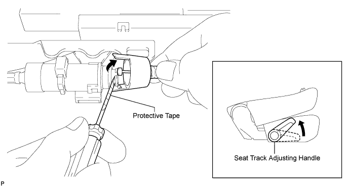
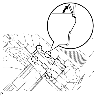
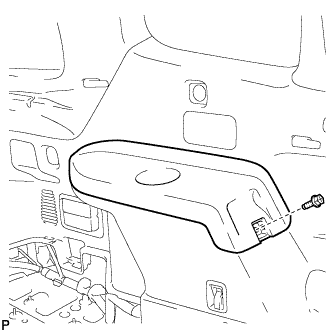
Pull down the adjuster's lock piece to release the lock as shown in the illustration.
-
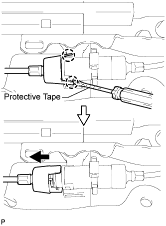
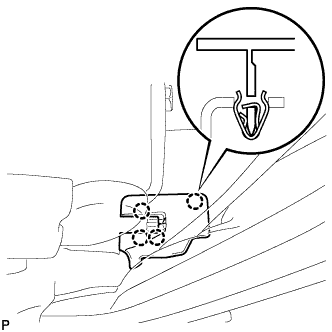
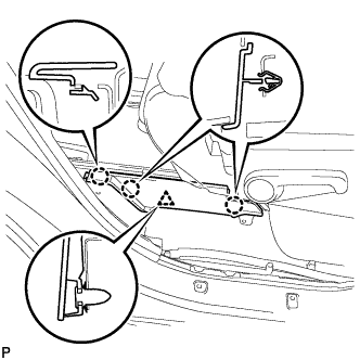
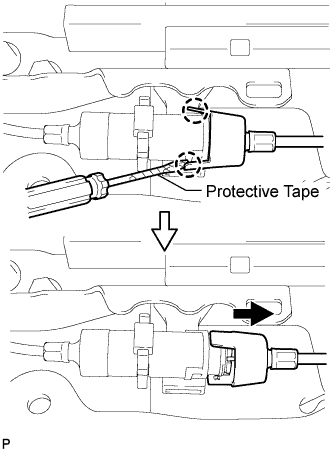
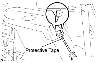
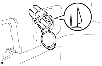
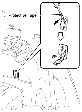
Using a screwdriver wrapped with protective tape, disengage the 2 claws as shown in the illustration.
-
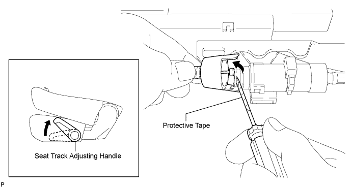
Lift up the seat track adjusting handle to the uppermost position and hold the handle in this position as shown in the illustration.
-
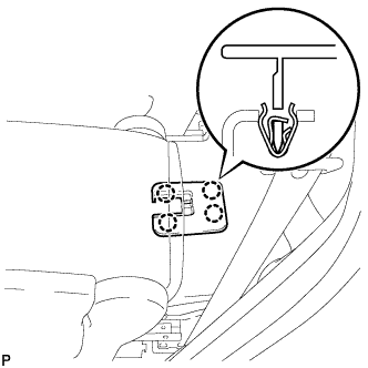
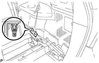
Using a screwdriver wrapped with protective tape, disconnect the rear No. 1 seat lock cable assembly as shown in the illustration.
-
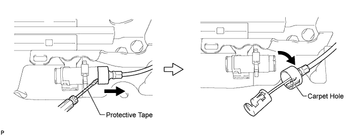
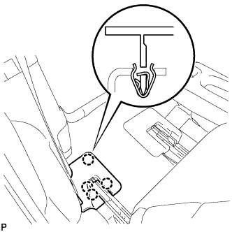
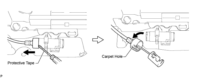
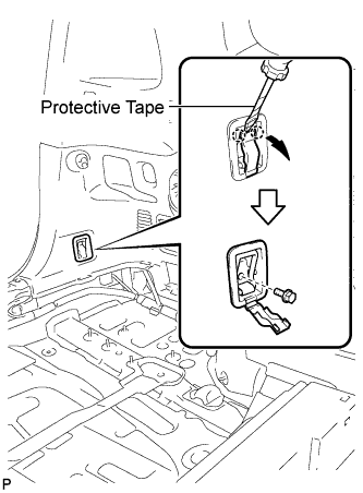
Using a screwdriver wrapped with protective tape, disconnect the rear seat reclining control cable as shown in the illustration.
-
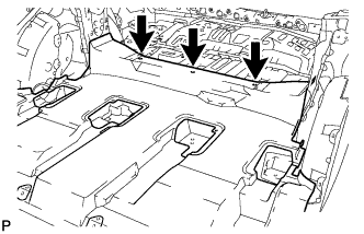
Secure the rear seat reclining control cable with the carpet hole as shown in the illustration.
-
- Click here
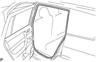
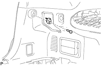
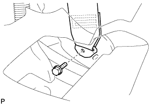
REMOVE REAR NO. 1 SEAT ASSEMBLY LH
-
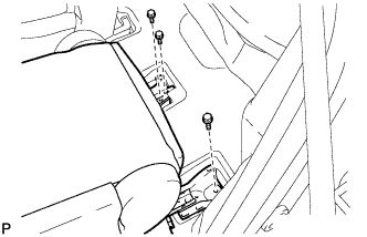
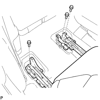
Remove the 3 bolts on the rear side of the seat.
-
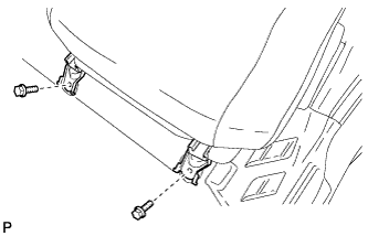
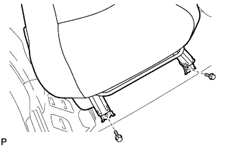
Remove the 2 bolts on the front side of the seat and the rear No. 1 seat assembly.
Note:Be careful not to damage the vehicle body.
-
- Click here
REMOVE REAR SEAT HEADREST ASSEMBLY (for RH Side)
- Click here
REMOVE SEAT TRACK BRACKET COVER RH
-
Disengage the 8 claws and remove the 2 rear seat track bracket covers.
-
- Click here
REMOVE REAR OUTER TRACK BRACKET COVER RH
-
Disengage the 4 claws and remove the rear outer track bracket cover.
-
- Click here
REMOVE REAR INNER TRACK BRACKET COVER RH
-
Disengage the 4 claws and remove the rear inner track bracket cover.
-
- Click here
REMOVE REAR SEAT LEG SIDE COVER RH
-
Disengage the 3 claws.
-
Disengage the clip and remove the rear seat leg side cover.
-
- Click here
DISCONNECT REAR NO. 1 SEAT LOCK CABLE ASSEMBLY RH (w/ Remote Folding Function)
-
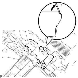
Pull down the adjuster's lock piece to release the lock as shown in the illustration.
-
Using a screwdriver wrapped with protective tape, disengage the 2 claws as shown in the illustration.
-
Lift up the seat track adjusting handle to the uppermost position and hold the handle in this position as shown in the illustration.
-
Using a screwdriver wrapped with protective tape, disconnect the rear No. 1 seat lock cable assembly as shown in the illustration.
-
Using a screwdriver wrapped with protective tape, disconnect the rear seat reclining control cable as shown in the illustration.
-
Secure the rear seat reclining control cable with the carpet hole as shown in the illustration.
-
- Click here
REMOVE REAR NO. 1 SEAT ASSEMBLY RH
-
Remove the 3 bolts on the rear side of the seat.
-
Remove the 2 bolts on the front side of the seat and the rear No. 1 seat assembly.
Note:Be careful not to damage the vehicle body.
-
- Click here
REMOVE REAR DOOR SCUFF PLATE LH
-
Disengage the 5 claws, 3 clips and guide, and remove the rear door scuff plate LH.
-
- Click here
DISCONNECT REAR DOOR OPENING TRIM WEATHERSTRIP LH
-
Remove the rear door opening trim weatherstrip LH.
-
- Click here
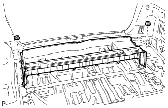
REMOVE DECK BOARD ASSEMBLY
-
Remove the deck board assembly.
-
- Click here
REMOVE NO. 3 DECK BOARD SUB-ASSEMBLY
-
Disengage the 2 guides and remove the No. 3 deck board sub-assembly.
-
- Click here
REMOVE NO. 2 DECK BOARD SUB-ASSEMBLY
-
Disengage the 2 guides and remove the No. 2 deck board sub-assembly.
-
- Click here
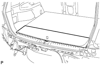
REMOVE TONNEAU COVER ASSEMBLY (w/ Tonneau Cover)
- Click here
REMOVE REAR NO. 1 FLOOR BOARD (w/o Rear No. 2 Seat)
-
Disengage the 3 clips and the 3 guides, and remove the rear No. 1 floor board.
-
- Click here
REMOVE REAR SEAT SIDE COVER LH (w/ Rear No. 2 Seat)
-
Disengage the 2 clips and remove the rear seat side cover LH.
-
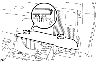
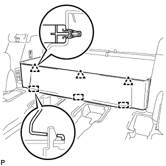
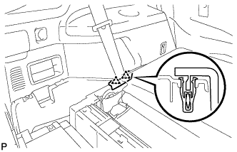
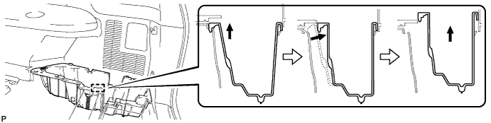
- Click here
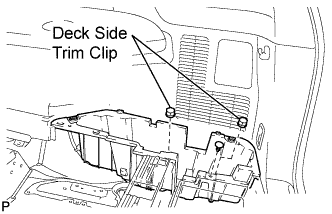
REMOVE DECK SIDE TRIM BOX LH
-
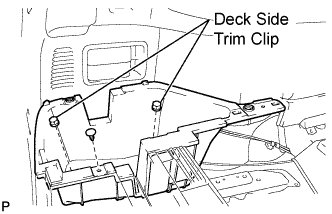
Remove the 2 deck side trim clips and clip.
-
Remove the deck side trim box LH as shown in the illustration.
-
- Click here
REMOVE REAR SEAT SIDE COVER RH (w/ Rear No. 2 Seat)
-
Disengage the 2 clips and remove the rear seat side cover RH.
-
- Click here
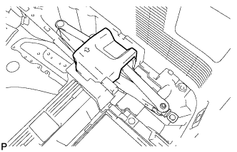
REMOVE JACK CARRIER SUPPORT
- Click here
REMOVE JACK CARRIER CUSHION (for LHD)
-
Remove the jack carrier cushion.
-
- Click here
REMOVE JACK CARRIER CUSHION (for RHD)
-

Remove the jack carrier cushion.
-
- Click here
REMOVE JACK ASSEMBLY (for LHD)
-
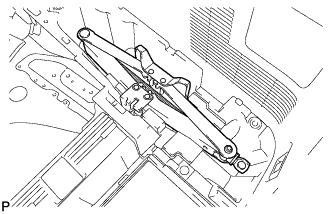
Remove the jack assembly.
-
- Click here
REMOVE JACK ASSEMBLY (for RHD)
-
Remove the jack assembly.
-
- Click here
REMOVE JACK CARRIER ASSEMBLY (for LHD)
-
Using a screwdriver, disengage the 3 claws and remove the jack carrier assembly.
-
- Click here
REMOVE JACK CARRIER ASSEMBLY (for RHD)
-
Using a screwdriver, disengage the 3 claws and remove the jack carrier assembly.
-
- Click here
REMOVE DECK SIDE TRIM BOX RH
-
Remove the 2 deck side trim clips and clip.
-
Remove the deck side trim box RH as shown in the illustration.
-
- Click here
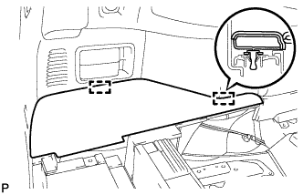
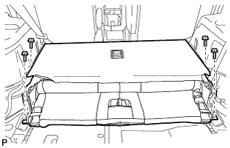
REMOVE DECK FLOOR BOARD ASSEMBLY (w/o Rear No. 2 Seat)
-
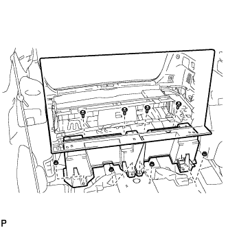
Remove the 4 bolts and 4 nuts.
-
Remove the deck floor board assembly.
-
- Click here
REMOVE REAR MAT
-
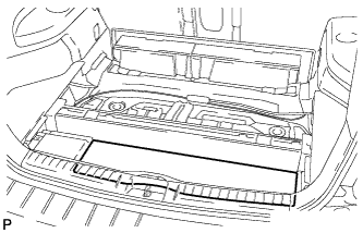
Remove the rear mat.
-
- Click here
REMOVE DECK FLOOR BOARD ASSEMBLY (w/ Rear No. 2 Seat)
-
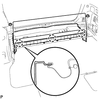
Disengage the 3 claws.
-
Remove the 2 nuts and the deck floor board assembly.
-
- Click here
REMOVE REAR DECK FLOOR BOX (w/o Rear No. 2 Seat)
-
Remove the 2 nuts and the deck floor box.
-
- Click here
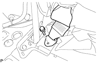
REMOVE REAR NO. 2 SEAT INNER BELT ASSEMBLY (w/ Rear No. 2 Seat)
-
Remove the bolt and rear No. 2 seat inner belt assembly.
Tip:Use the same procedure for the RH side and LH side.
-
- Click here
DISCONNECT REAR SEAT LAP TYPE BELT ASSEMBLY LH (w/ Rear No. 2 Seat)
-
Remove the bolt and disconnect the rear seat lap type belt assembly LH.
-
- Click here
DISCONNECT REAR SEAT LAP TYPE BELT ASSEMBLY RH (w/ Rear No. 2 Seat)
Tip:Use the same procedure for the RH side and the LH side.
- Click here
REMOVE REAR NO. 2 SEAT ASSEMBLY (w/ Rear No. 2 Seat)
-
Remove the 4 bolts and the rear No. 2 seat assembly.
-
- Click here
REMOVE REAR FLOOR FINISH PLATE
-
Disengage the 4 clips and the 4 claws, and remove the rear floor finish plate.
-
- Click here
REMOVE DECK SIDE TRIM COVER NO.2
-
Using a screwdriver, disengage the 2 claws and remove the deck side trim cover LH.
Tip:Tape the screwdriver tip before use.
-
- Click here
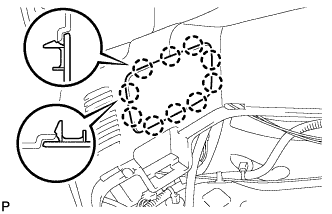
REMOVE DECK SIDE TRIM LH
-
Remove the bolt.
-
Disengage the 4 claws and the 3 guides, and remove the deck side trim LH as shown in the illustration.
-
- Click here
REMOVE SIDE TRIM COVER LH
-
Disengage the 10 claws and remove the side trim cover LH.
-
- Click here
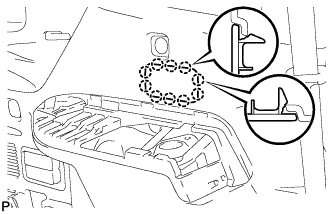
REMOVE REAR COMBINATION LIGHT SERVICE COVER LH
-

Using a screwdriver, disengage the 6 claws and 2 guides, and remove the rear combination light service cover LH.
Tip:Tape the screwdriver tip before use.
-
- Click here
REMOVE REAR POWER POINT SOCKET ASSEMBLY
-
Disconnect the connector.
-
Disengage the claw and remove the rear power point socket assembly.
-
- Click here
REMOVE REAR POWER OUTLET SOCKET COVER
-
Disengage the 2 claws and remove the rear power outlet socket cover.
-
- Click here
REMOVE REAR DECK TRIM COVER (w/o Remote Folding Function)
-
Disengage the 10 claws and remove the rear deck trim cover.
-
- Click here
REMOVE RECLINING REMOTE CONTROL LEVER BEZEL LH (w/ Remote Folding Function)
-
Disengage the 5 claws and remove the reclining remote control bezel LH.
-
- Click here
REMOVE ROPE HOOK ASSEMBLY (for LH Side)
-
for Front Side:
-
Using a screwdriver, disengage the 2 claws.
Tip:Tape the screwdriver tip before use.
-
Remove the bolt and the rope hook assembly.
-
-
for Rear Side:
-
Using a screwdriver, disengage the 2 claws.
Tip:Tape the screwdriver tip before use.
-
Remove the bolt and rope hook assembly.
-
-
- Click here
REMOVE NO. 2 DECK SIDE TRIM HOOK
-
Remove the screw and the No. 2 deck side trim hook.
-
- Click here
REMOVE FRONT DECK SIDE TRIM COVER LH
-
Using a screwdriver, disengage the 4 claws and remove the 2 front deck side trim covers LH.
Tip:Tape the screwdriver tip before use.
-
- Click here
DISCONNECT REAR NO. 1 SEAT OUTER BELT ASSEMBLY LH
-
Remove the bolt and disconnect the floor end of the rear No. 1 seat outer belt assembly.
-
- Click here
REMOVE DECK TRIM SIDE PANEL ASSEMBLY LH
-
Remove the 2 bolts.
-
Remove the 2 clips.
-
Disengage the 7 claws and 4 clips, and remove the deck trim side panel assembly LH.
-
- Click here
REMOVE REAR FLOOR SERVICE HOLE COVER
-
Lift up the front floor carpet.
-
Using a clip remover, remove the 3 clips and lift up the front floor carpet. (w/ rear No. 2 seat)
-
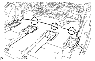
Disengage the 3 claws and lift up the front floor carpet. (w/o rear No. 2 seat)
-
-
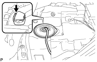
Remove the rear floor service hole cover.
-
Disconnect the fuel pump connector.
-
- Click here
REMOVE FUEL SUCTION TUBE ASSEMBLY WITH PUMP AND GAUGE
-
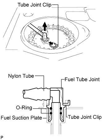
Remove the tube joint clip, and pull out the fuel pump tube.
Note:
-
Check that there is no dirt or other foreign objects around the connector before disconnecting it. Clean the connector if necessary.
-
It is necessary to prevent mud or dirt from entering the quick connector. If mud or dirt gets in the connector, the O-rings may not seal properly.
-
Disconnect the quick connector by hand. Do not use any tools
-
Do not bend, kink or twist the nylon tubes. Protect the connector by covering it with a plastic bag.
-
If the pipe and connector are stuck, carefully try wiggling or pushing and pulling on the connector to release it. Pull the connector off carefully.
-
-
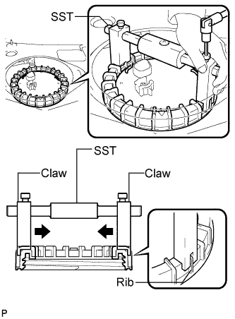
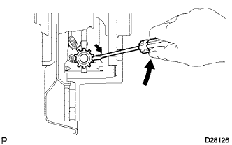
Using a 6 mm socket hexagon wrench, install SST to the fuel pump gauge retainer.
09808-14020 09808-01410 09808-01420 09808-01430 Tip:
-
Engage the SST claws securely with the fuel pump gauge retainer ribs to secure SST.
-
Install SST while pressing the SST claws toward the fuel pump gauge retainer (toward the center of SST).
-
-
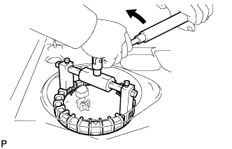
Using SST, loosen the fuel pump gauge retainer.
09808-14020 09808-01410 09808-01420 09808-01430 Note:
-
Do not use any tools other than specified in this operation. Damage to the fuel pump gauge retainer or the fuel tank may result.
-
Loosen the retainer by turning it counterclockwise while holding SST down. Do not allow the claw of the tank suction tube support to slip out of its groove on the fuel tank.
Tip:The ribs on the fuel pump gauge retainer can be fitted into the tips of SST.
-
-
Remove the fuel pump gauge retainer.
-
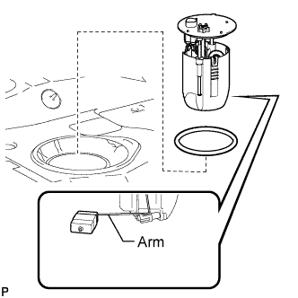
Remove the fuel suction tube with pump and gauge.
Note:Be careful not to bend the arm of the fuel sender gauge.
-
Remove the gasket from the fuel tank.
-
- Click here
DRAIN FUEL
- Click here
REMOVE FRONT CENTER FLOOR COVER
-
Remove the 4 bolts, 2 screws, and the nut.
-
Disengage the 4 clips and remove the center front floor cover.
-
- Click here
REMOVE TAIL EXHAUST PIPE ASSEMBLY
-
Remove the 2 bolts and 2 compression springs.
-
Disconnect the exhaust pipe support and remove the tail exhaust pipe assembly.
-
Remove the gasket from the center exhaust pipe assembly.
-
- Click here
REMOVE CENTER EXHAUST PIPE ASSEMBLY
-
Remove the 2 bolts and 2 compression springs.
-
Disconnect the 3 exhaust pipe supports and remove the center exhaust pipe assembly.
-
Remove the gasket from the No. 3 exhaust pipe sub-assembly.
-
- Click here
REMOVE NO. 4 EXHAUST PIPE SUPPORT BRACKET
-
Remove the 2 bolts, and then remove the No. 4 exhaust pipe support bracket.
-
- Click here
REMOVE PROPELLER WITH CENTER BEARING SHAFT ASSEMBLY (for 4WD)
-
Depress the brake pedal and hold it.
-
Using a hexagon wrench (6 mm), loosen the cross groove joint set bolts 1/2 turn.
Tip:Put a piece of cloth or equivalent into the inside of the universal joint cover so that the boot does not touch the inside of the universal joint cover.
-
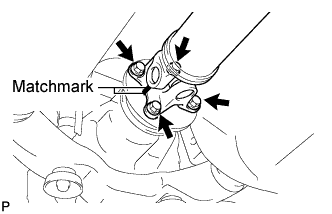
Place matchmarks on the rear propeller shaft and rear drive pinion flange sub-assembly.
-
Remove the 4 nuts, 4 bolts and 4 washers.
-
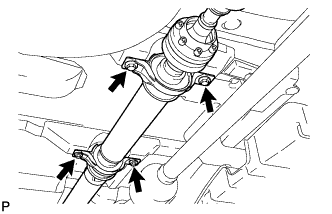
Remove the 4 bolts and 4 adjusting shims.
-
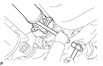
Using a brass bar and a hammer, remove the propeller shaft with center bearing shaft assembly.
-
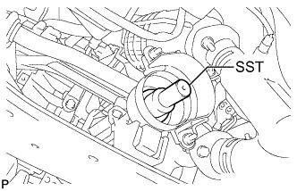
Insert SST into the transfer to prevent oil leakage.
09325-20010
-
- Click here
REMOVE REAR WHEELS (for 4WD)
- Click here
SEPARATE REAR SPEED SENSOR LH (for 4WD)
-
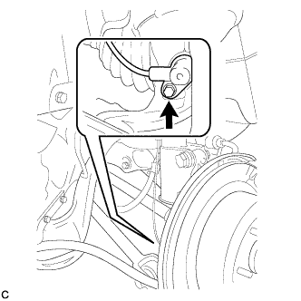
Remove the bolt and separate the rear speed sensor from the rear axle carrier sub-assembly.
Note:Keep the sensor tip and rear speed sensor installation hole free from foreign matter.
-
- Click here
SEPARATE REAR SPEED SENSOR RH (for 4WD)
Tip:Perform the same procedure as the LH side.
- Click here
REMOVE REAR AXLE SHAFT NUT LH (for 4WD)
-
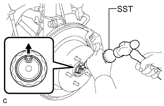
Using SST and a hammer, release the staked part of the rear axle shaft nut.
09930-00010 Note:Loosen the staked part of the nut completely, otherwise the threads of the drive shaft may be damaged.
-
While applying the brakes, remove the rear axle shaft nut.
-
- Click here
REMOVE REAR AXLE SHAFT NUT RH (for 4WD)
Tip:Perform the same procedure as the LH side.
- Click here
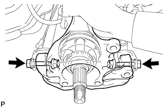
REMOVE REAR DISC BRAKE CALIPER ASSEMBLY LH (for 4WD)
-
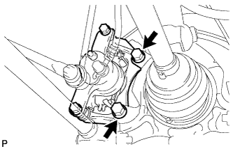
Remove the 2 bolts and separate the rear disc brake caliper assembly.
Note:Use wire or an equivalent tool to keep the brake caliper from hanging down by the flexible hose.
-
- Click here
REMOVE REAR DISC BRAKE CALIPER ASSEMBLY RH (for 4WD)
Tip:Perform the same procedure as the LH side.
- Click here
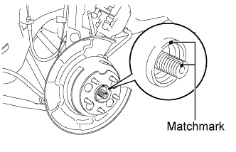
REMOVE REAR DISC (for 4WD LH Side)
-
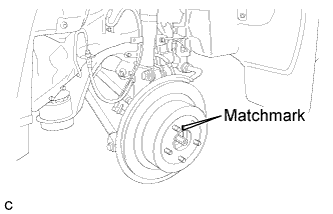
Put matchmarks on the rear disc and the axle hub.
-
Release the parking brake and remove the rear disc.
Tip:If the disc cannot be removed easily, turn and press firmly the shoe adjuster until the wheel comes free.
-
- Click here
REMOVE REAR DISC (for 4WD RH Side)
- Click here
REMOVE REAR AXLE HUB AND BEARING ASSEMBLY LH (for 4WD)
-
Put matchmarks on the drive shaft and axle hub.
Note:Do not punch the marks.
-
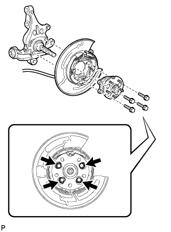
Remove the 4 bolts and the rear axle hub and bearing assembly.
Note:
-
Do not rotate the drive shaft with the rear axle hub and bearing assembly removed.
-
Use wire or an equivalent tool to keep the parking brake assembly from hanging down by the parking brake cable assembly.
-
-
- Click here
REMOVE REAR AXLE HUB AND BEARING ASSEMBLY RH (for 4WD)
Tip:Perform the same procedure as the LH side.
- Click here
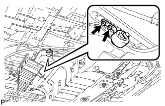
REMOVE NO. 3 PARKING BRAKE CABLE ASSEMBLY (for 4WD)
-
Remove the bolt and the nut, and separate the No. 3 parking brake cable assembly.
-
- Click here
REMOVE NO. 2 PARKING BRAKE CABLE ASSEMBLY (for 4WD)
Tip:Perform the same procedure as the No. 3 parking brake cable assembly.
- Click here
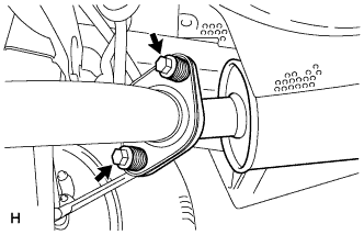
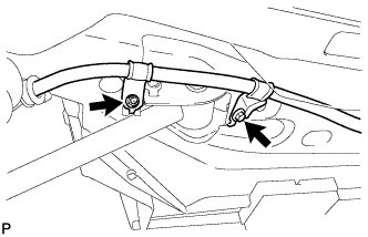
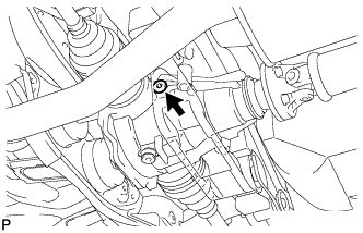
REMOVE REAR STRUT ROD ASSEMBLY LH (for 4WD)
-
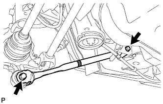
Remove the 2 bolts, the 2 nuts, and the rear strut rod assembly.
Note:Since stopper nuts are used, loosen the bolts.
-
- Click here
REMOVE REAR STRUT ROD ASSEMBLY RH (for 4WD)
Tip:Perform the same procedure as the LH side.
- Click here
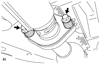
REMOVE REAR AXLE CARRIER SUB-ASSEMBLY LH (for 4WD)
-
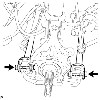
Loosen the 2 bolts.
Note:Since stopper nuts are used, loosen the bolts.
-
Remove the 2 bolts and 2 nuts, and separate the rear shock absorber with coil spring (lower side) from the rear axle carrier sub-assembly.
Note:
-
Be careful not to damage the outboard joint boot.
-
Be careful not to damage the speed sensor rotor.
-
-
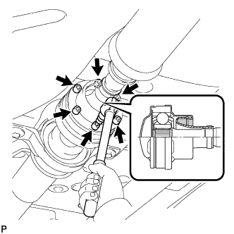
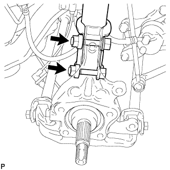
Remove the 2 bolts, the 2 nuts, and the rear axle carrier sub-assembly.
Note:
-
Be careful not to damage the outboard joint boot.
-
Be careful not to damage the speed sensor rotor.
Tip:Use wire or an equivalent tool to keep the rear drive shaft assembly from hanging down.
-
-
- Click here
REMOVE REAR AXLE CARRIER SUB-ASSEMBLY RH (for 4WD)
Tip:Perform the same procedure as the LH side.
-
Click here
REMOVE REAR NO. 2 SUSPENSION ARM ASSEMBLY LH (for 4WD)
-
Put matchmarks on the adjust cams and the rear suspension member sub-assembly.
-
Remove the nut, the No. 2 camber adjust cam, the rear suspension toe adjust cam sub-assembly, and the rear No. 2 suspension arm assembly LH.
Note:Mark the removed parts to distinguish left from right and keep them in order for reinstallation.
Tip:When removing the nut, keep the rear suspension toe adjust cam sub-assembly from rotating.
-
- Click here
REMOVE REAR NO. 2 SUSPENSION ARM ASSEMBLY RH (for 4WD)
Tip:Perform the same procedure as the LH side.
-
Click here
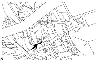
REMOVE REAR NO. 1 SUSPENSION ARM ASSEMBLY RH (for 4WD)
-
Remove the bolt, the nut, and the rear No. 1 suspension arm assembly RH from the rear suspension member sub-assembly.
Note:
-
Since a stopper nut is used, loosen the bolt.
-
Mark the removed parts to distinguish left from right and keep them in order for reinstallation.
-
-
- Click here
REMOVE REAR DIFFERENTIAL FILLER PLUG (for 4WD)
-
Using a hexagon wrench (10 mm), remove the rear differential filler plug and rear differential filler plug gasket.
-
- Click here
REMOVE REAR DIFFERENTIAL DRAIN PLUG (for 4WD)
-
Using a hexagon wrench (10 mm), remove the rear differential drain plug and rear differential drain plug gasket, and drain the oil.
-
- Click here
REMOVE REAR DRIVE SHAFT ASSEMBLY LH (for 4WD)
-
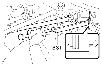
Using SST, remove the rear drive shaft assembly as shown in the illustration.
09520-01010 09520-24010 09520-32040 Note:Remove the rear drive shaft assembly while keeping it level.
-
- Click here
REMOVE REAR DRIVE SHAFT SNAP RING LH (for 4WD)
-
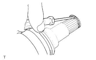
Using a screwdriver, remove the rear drive shaft snap ring.
-
- Click here
REMOVE REAR DRIVE SHAFT ASSEMBLY RH (for 4WD)
Tip:Perform the same procedure as the LH side.
- Click here
REMOVE REAR DRIVE SHAFT SNAP RING RH (for 4WD)
Tip:Perform the same procedure as the LH side.
- Click here
REMOVE REAR SUSPENSION MEMBER (for 4WD)
-
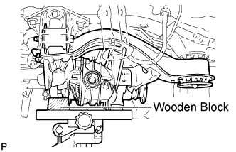
Support the rear suspension member with a jack using a wooden block.
Tip:Use a properly sized wooden block to keep the jack and suspension member level.
-
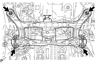
Remove the 4 nuts, 2 bolts and 2 rear lower suspension member stopper retainers.
-
Lower the rear suspension member.
-
Remove the 2 rear upper suspension member stoppers.
-
- Click here
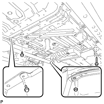
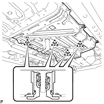
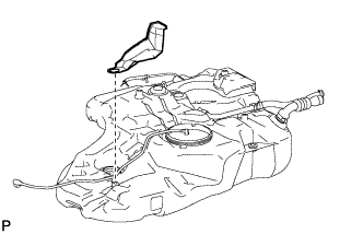
REMOVE NO. 1 FUEL TANK PROTECTOR SUB-ASSEMBLY
-
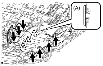
Remove the 3 clips (A) and 7 nuts, and then remove the No. 1 fuel tank protector sub-assembly.
-
- Click here
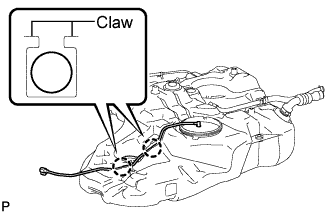
REMOVE FUEL TANK ASSEMBLY
-
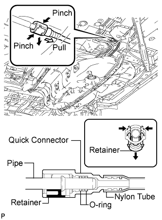
Disconnect the fuel pump tube.
-
Pinch the tab of the retainer to disengage the lock claws and pull it down as shown in the illustration.
-
Pull out the fuel pump tube.
Note:
-
Check if there is any dirt or mud around the connector before this operation and clean the connector if necessary.
-
It is necessary to prevent mud or dirt from entering the quick connector. If any foreign objects enter the connector, the O-rings may seal properly.
-
Do not use any tool in this operation.
-
Do not bend or twist the nylon tube. Protect the connector by covering it with a plastic bag.
-
When the pipe and connector are stuck, push and pull the connector to release it and pull the connector out carefully.
-
-
-
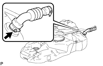
Disconnect the fuel tank vent hose.
-
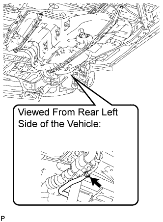
Slide the clamp and disconnect the fuel tank vent hose.
-
-
Disconnect the No. 3 fuel tank breather tube.
-
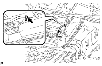
Loosen the hose clamp bolt and disconnect the No. 3 fuel tank breather tube.
-
-
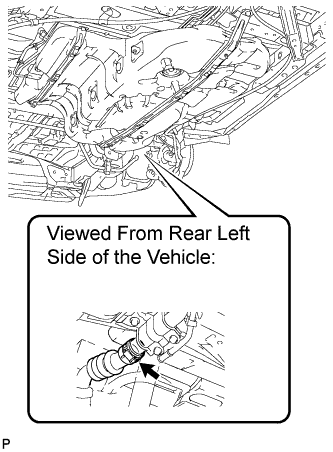
Loosen the hose clamp bolt and disconnect the fuel tank to filler pipe hose.
-
Set a transmission jack under the fuel tank.
-
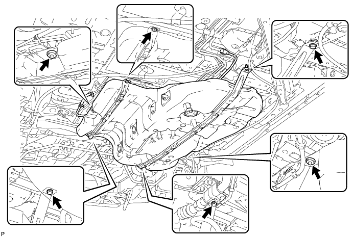
Remove the 4 bolts, and then remove the 2 fuel tank bands.
-
Remove the 2 nuts.
-
Operate the transmission jack to remove the fuel tank.
-
- Click here
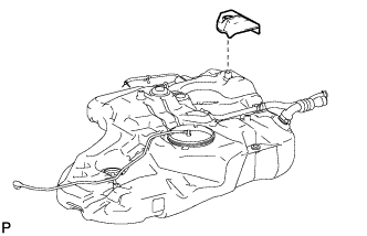
REMOVE REAR FUEL TANK SIDE PLATE
-
Remove the rear fuel tank side plate.
-
- Click here
REMOVE NO. 1 FUEL TANK CUSHION
-
Remove the No. 1 fuel tank cushion.
-
- Click here
REMOVE FUEL PUMP TUBE SUB-ASSEMBLY
-
Release the 2 claws, and then remove the fuel pump tube.
-
- Click here
REMOVE FUEL TANK TO FILLER PIPE HOSE
-
Loosen the hose clamp bolt, and then remove the fuel tank to filler pipe hose.
-
- Click here
REMOVE TANK SUCTION TUBE SUPPORT
-
Remove the tank suction tube support from the fuel tank.
-
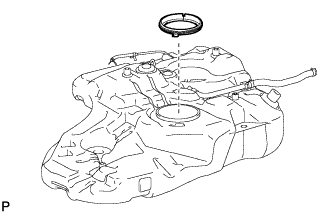
- Click here
REMOVE FUEL TANK SIDE PLATE
-
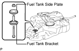
Remove the bolt and nut, and then remove the fuel tank side plate and the fuel tank bracket.
-
- Click here
REMOVE FUEL TANK CUSHION SET
-
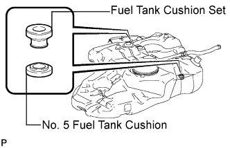
Remove the 2 fuel tank cushion sets and 2 No. 5 fuel tank cushions.
-