- Click here
INSTALL FUEL SUCTION TUBE ASSEMBLY WITH PUMP AND GAUGE
-
Install a new gasket to the fuel tank.
-
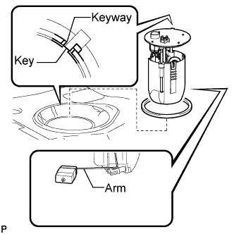
Attach the fuel suction tube with pump and gauge to the fuel tank.
Note:Be careful not to bend the arm of the fuel sender gauge.
-
Align the keyway of the fuel suction tube support with the key of the fuel suction tube with pump and gauge.
-

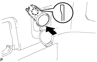
Align the triangle mark on a new fuel pump gauge retainer with the "S" mark on the fuel tank while pushing down the fuel suction tube with pump and gauge, and attach the fuel pump gauge retainer.
-
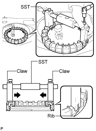
Using a 6 mm socket hexagon wrench, install SST to the fuel pump gauge retainer.
09808-14020 09808-01410 09808-01420 09808-01430 Tip:
-
Engage the SST claws securely with the fuel pump gauge retainer ribs to secure SST.
-
Install SST while pressing the SST claws toward the fuel pump gauge retainer (toward the center of SST).
-
-
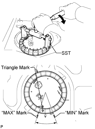
Rotate the fuel pump gauge retainer by hand, then tighten it one complete turn and another half turn using SST. The triangle mark on the fuel pump gauge retainer must be positioned between the "MIN" and "MAX" marks on the fuel tank.
09808-14020 09808-01410 09808-01420 09808-01430 Note:
-
Do not use any tools other than specified in this operation. Damage to the fuel pump gauge retainer or the fuel tank may result.
-
Fully tighten the retainer by turning it clockwise while holding SST down. Do not allow the claw of the tank suction tube support to slip out of its groove on the fuel tank.
Tip:The ribs on the fuel pump gauge retainer can be fitted into the tips of SST.
-
-
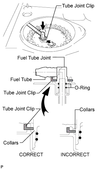
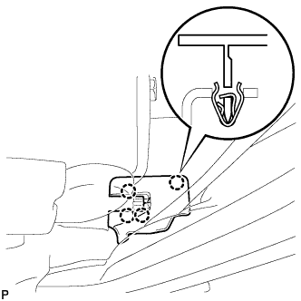
Install the fuel pump tube and the tube joint clip.
Note:
-
Check that there are no scratches or foreign objects on the connecting part.
-
Check that the fuel tube joint is inserted securely.
-
Check that the tube joint clip is correctly located on the collar of the fuel tube joint.
-
After installing the tube joint clip, check that the fuel tube joint has not been pulled out of position.
-
-
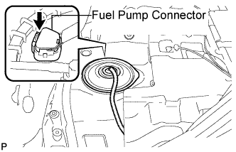
Connect the fuel pump connector.
-
- Click here
CONNECT CABLE TO NEGATIVE BATTERY TERMINAL
- Click here
INSPECT FUEL LEAK
-
Check fuel pump operation.
-
Connect the intelligent tester to the DLC3.
-
Turn the ignition switch on (IG) and turn the intelligent tester main switch on.
Note:Do not start the engine.
-
Select the following menu items: DIAGNOSIS / ENHANCED OBD II / ACTIVE TEST / FUEL PUMP / SPD.
-
Check for pressure in the fuel inlet tube from the fuel line. Check that sounds of fuel flowing from the fuel tank can be heard. If no sounds can be heard, check the integration relay, fuel pump, ECM and wiring connectors.
-
-
Check for fuel leaks.
-
Check that there are no fuel leaks from the fuel system after doing any maintenance or repairs. If there is a fuel leak, repair or replace parts as necessary.
-
-
Turn the ignition switch off.
-
Disconnect the intelligent tester from the DLC3.
-
- Click here
DISCONNECT CABLE FROM NEGATIVE BATTERY TERMINAL
Note:When disconnecting the cable, some systems need to be initialized after the cable is reconnected (Click here).
- Click here
INSTALL REAR FLOOR SERVICE HOLE COVER
-
Install new butyl tape to the rear floor service hole cover.
-
Install the rear floor service hole cover.
-
Install the front floor carpet.
-
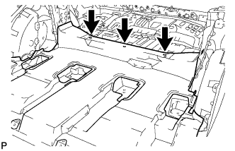
Install the front floor carpet with the 3 clips. (w/ rear No. 2 seat)
-
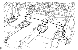
Engage the 3 claws to install the front floor carpet. (w/o rear No. 2 seat)
-
-
- Click here
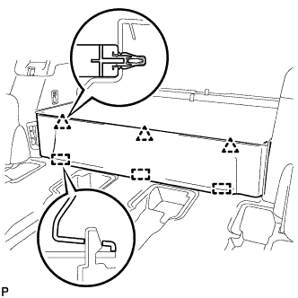
INSTALL DECK TRIM SIDE PANEL ASSEMBLY LH
-
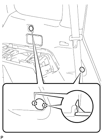
Engage the 4 clips and 7 claws.
-
Install the 2 clips.
-
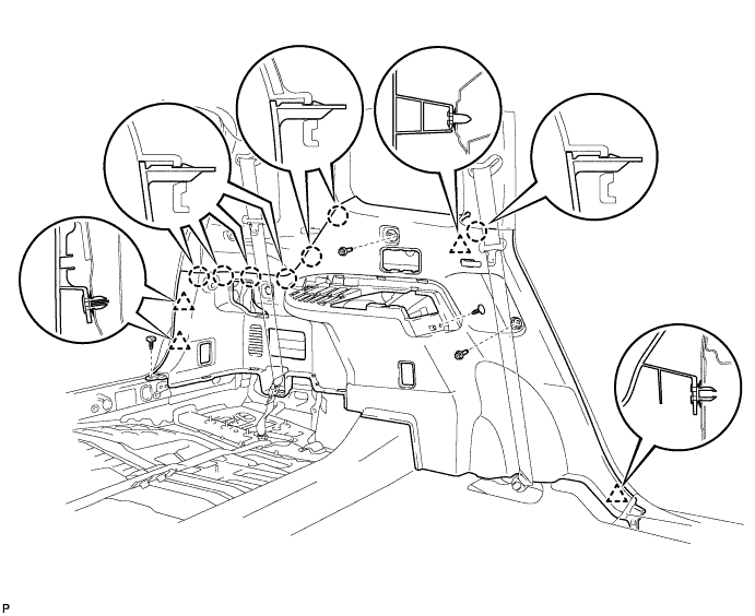
Install the deck trim side panel assembly LH with the 2 bolts.
-
- Click here
CONNECT REAR NO. 1 SEAT OUTER BELT ASSEMBLY LH
-
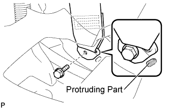
Connect the floor anchor end of the rear No. 1 seat outer belt assembly and install the bolt.
42 N*m 428 kgf*cm 31 ft.*lbf Note:Do not allow the anchor part of the rear No. 1 seat outer belt assembly to overlap the protruding part of the floor panel.
-
- Click here
INSTALL FRONT DECK SIDE TRIM COVER LH
-
Engage the 4 claws and install the 2 front deck side trim covers LH.
-
- Click here
INSTALL NO. 2 DECK SIDE TRIM HOOK
-
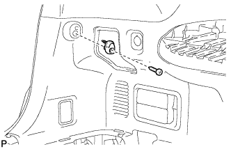
Install the No. 2 deck side trim hook with the screw.
-
- Click here
INSTALL ROPE HOOK ASSEMBLY (for LH Side)
-
for Front Side:
-
Install the rope hook assembly with the bolt.
6.5 N*m 66 kgf*cm 58 in.*lbf -
Engage the 2 claws.
-
-
for Rear Side:
-
Install the rope hook assembly with the bolt.
6.5 N*m 66 kgf*cm 58 in.*lbf -
Engage the 2 claws.
-
-
- Click here
INSTALL REAR DECK TRIM COVER (w/o Remote Folding Function)
-
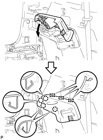
Engage the 10 claws to install the rear deck trim cover.
-
- Click here
INSTALL RECLINING REMOTE CONTROL LEVER BEZEL LH (w/ Remote Folding Function)
-
Engage the 5 claws to install the reclining remote control lever bezel LH.
-
- Click here
INSTALL REAR POWER OUTLET SOCKET COVER
-
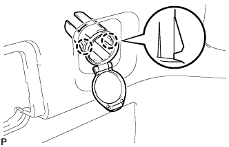
Engage the 2 claws and install the rear power outlet socket cover.
-
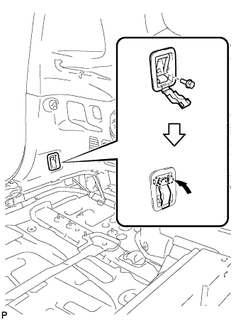
- Click here
INSTALL REAR POWER POINT SOCKET ASSEMBLY
-
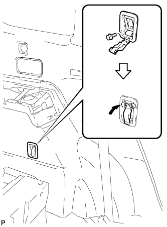
Engage the claw and install the rear power point socket assembly.
-
Connect the connector.
-
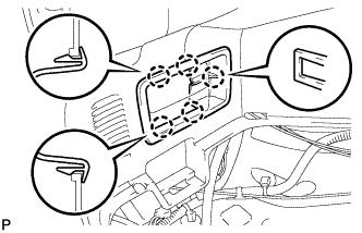
- Click here
INSTALL REAR COMBINATION LIGHT SERVICE COVER LH
-
Engage the 2 guides and 6 claws, and install the rear combination light service cover LH.
-
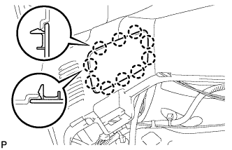
- Click here
INSTALL SIDE TRIM COVER LH
-
Engage the 10 claws and install the side trim cover LH.
-
- Click here
INSTALL DECK SIDE TRIM LH
-
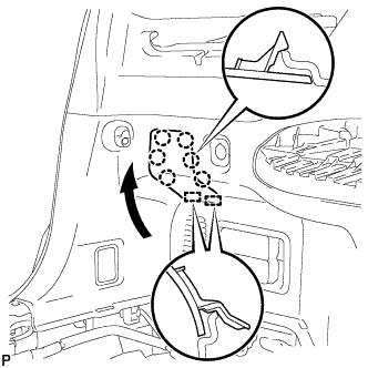
Engage the 3 guides and 4 claws as shown in the illustration.
-
Install the deck side trim LH with the bolt.
-
- Click here
INSTALL DECK SIDE TRIM COVER NO.2
-
Engage the 2 claws and install the deck side trim cover LH.
-
- Click here
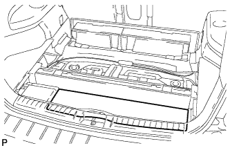
INSTALL REAR FLOOR FINISH PLATE
-
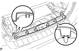
Engage the 4 clips and 4 claws, and install the rear floor finish plate.
-
- Click here
INSTALL REAR NO. 2 SEAT ASSEMBLY (w/ Rear No. 2 Seat)
-
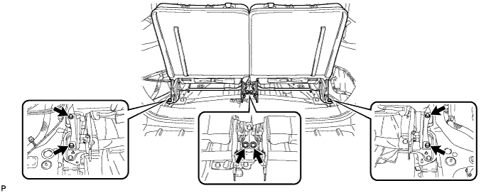
Install the 6 bolts on the rear of the seat.
37 N*m 377 kgf*cm 27 ft.*lbf -
Install the rear No. 2 seat assembly with the bolt.
37 N*m 377 kgf*cm 27 ft.*lbf
-
- Click here
INSTALL CENTER SEAT CUSHION COVER SUB-ASSEMBLY (w/ Rear No. 2 Seat)
-
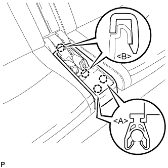
Engage the 2 claws <B>.
-
Engage the 2 claws <A> to install the center seat cushion cover sub-assembly.
-
- Click here
CONNECT REAR NO. 2 SEAT OUTER BELT ASSEMBLY RH (w/ Rear No. 2 Seat)
Tip:Use the same procedure as for the LH side.
- Click here
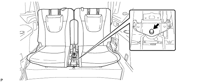
CONNECT REAR NO. 2 SEAT OUTER BELT ASSEMBLY LH (w/ Rear No. 2 Seat)
-
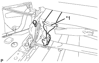
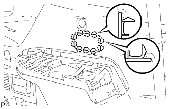
Route the rear No. 2 seat outer belt assembly LH through the rubber band as shown in the illustration.
Table 1. Text in Illustration *1 Rubber Band -
Install the rear No. 2 seat outer belt assembly LH with the bolt.
42 N*m 428 kgf*cm 31 ft.*lbf Note:After installing the belt, check that it is not twisted.
-
- Click here
INSTALL REAR DECK FLOOR BOX (w/o Rear No. 2 Seat)
-
Install the rear deck floor box with the 2 nuts.
-
- Click here
INSTALL DECK FLOOR BOARD ASSEMBLY (w/o Rear No. 2 Seat)
-
Install the 2 nuts and deck floor board assembly.
-
Engage the 3 claws.
-
- Click here
INSTALL REAR MAT
-
Install the rear mat.
-
- Click here
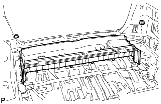
INSTALL DECK FLOOR BOARD ASSEMBLY (w/ Rear No. 2 Seat)
-

Install the rear deck floor board assembly with the 4 nuts and 4 bolts.
-
- Click here
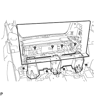
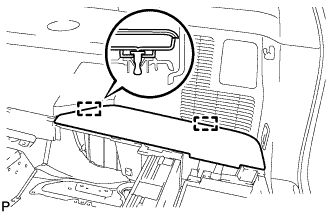
INSTALL DECK SIDE TRIM BOX LH
-
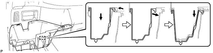
Install the deck side trim box LH as shown in the illustration.
-
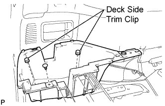
Install the 2 deck side trim clips and clip.
-
- Click here
INSTALL REAR SEAT SIDE COVER LH (w/ Rear No. 2 Seat)
-
Engage the 2 clips and install the rear seat side cover LH.
-
- Click here
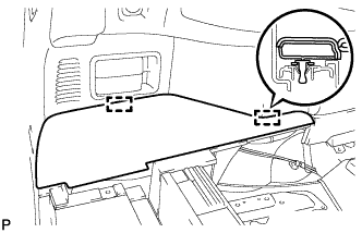
INSTALL DECK SIDE TRIM BOX RH
-
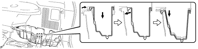
Install the deck side trim box RH as shown in the illustration.
-
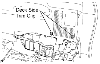
Install the 2 deck side trim clips and clip.
-
- Click here
INSTALL JACK CARRIER ASSEMBLY (for LHD)
-

Engage the 3 claws, and install the jack carrier assembly.
-
- Click here
INSTALL JACK CARRIER ASSEMBLY (for RHD)
-
Engage the 3 claws, and install the jack carrier assembly.
-
- Click here
INSTALL JACK ASSEMBLY (for LHD)
-
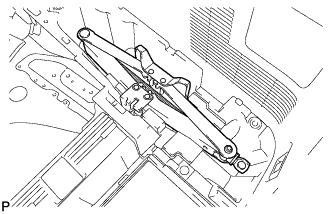
Install the jack assembly.
-
- Click here
INSTALL JACK ASSEMBLY (for RHD)
-
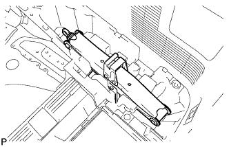
Install the jack assembly.
-
- Click here
INSTALL JACK CARRIER CUSHION (for LHD)
-
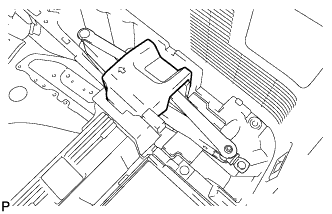
Install the jack carrier cushion.
-
- Click here
INSTALL JACK CARRIER CUSHION (for RHD)
-

Install the jack carrier cushion.
-
- Click here
INSTALL JACK CARRIER SUPPORT
- Click here
INSTALL REAR SEAT SIDE COVER RH (w/ Rear No. 2 Seat)
-
Engage the 2 clips and install the rear seat side cover RH.
-
- Click here
INSTALL REAR NO. 1 FLOOR BOARD (w/o Rear No. 2 Seat)
-
Engage the 3 guides and 3 clips and install the rear No. 1 floor board.
-
- Click here
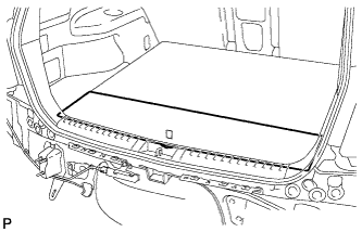
INSTALL TONNEAU COVER ASSEMBLY (w/ Tonneau Cover)
- Click here
INSTALL NO. 2 DECK BOARD SUB-ASSEMBLY
-
Engage the 2 guides and install the No. 2 deck board sub-assembly.
-
- Click here
INSTALL NO. 3 DECK BOARD SUB-ASSEMBLY
-
Engage the 2 guides and install the No. 3 deck board sub-assembly.
-
- Click here
INSTALL DECK BOARD ASSEMBLY
-
Install the deck board assembly.
-
- Click here
INSTALL REAR DOOR OPENING TRIM WEATHERSTRIP LH
-
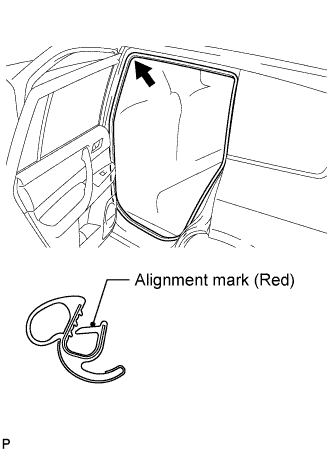
Align the alignment mark (red) on the weatherstrip with the protruding portion on the body indicated by the arrow in the illustration, and install the rear door opening trim weatherstrip LH.
Note:After installation, check that the corners fit correctly.
-
- Click here
INSTALL REAR DOOR SCUFF PLATE LH
-
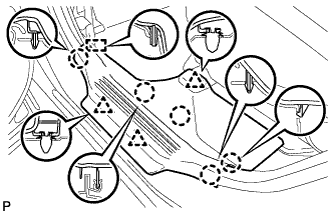
Engage the guide, 3 clips and 5 claws, and install the rear door scuff plate LH.
-
- Click here
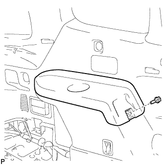
INSTALL REAR NO. 1 SEAT ASSEMBLY RH
-
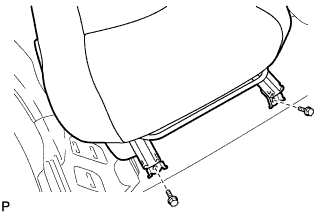
Temporarily install the 2 bolts on the front side of the seat.
-
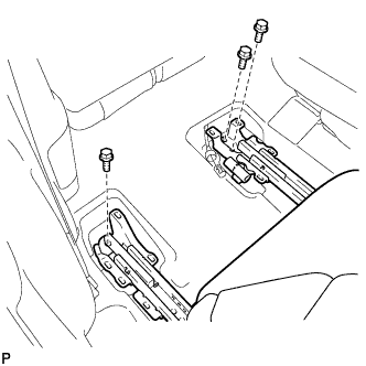
Temporarily Install the 3 bolts on the rear side of the seat.
-
Install the rear No. 1 seat assembly with the 5 bolts.
37 N*m 377 kgf*cm 27 ft.*lbf
-
- Click here
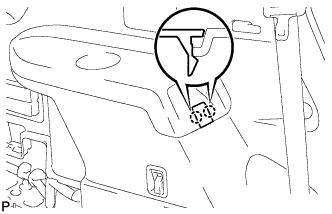
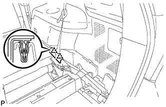
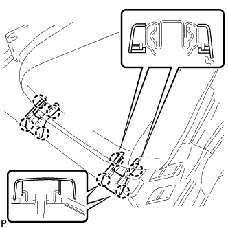
CONNECT REAR NO. 1 SEAT LOCK CABLE ASSEMBLY RH (w/ Remote Folding Function)
-
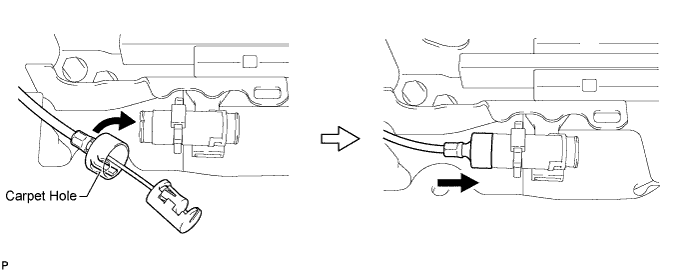
Remove the rear seat reclining control cable from the carpet hole.
-
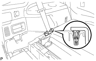
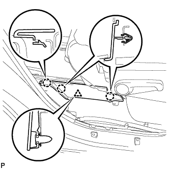
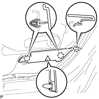
Connect the rear seat reclining control cable as shown in the illustration.
-
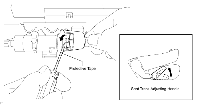
Connect the rear No. 1 seat lock cable assembly as shown in the illustration.
-
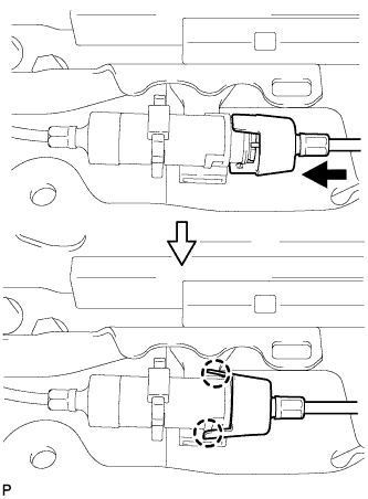
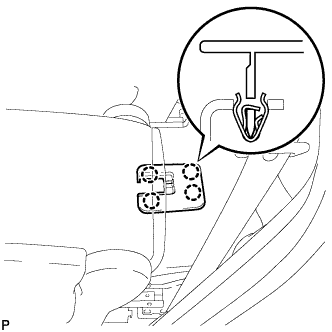
Engage the 2 claws and connect the rear No. 1 seat lock cable assembly as shown in the illustration.
-
Return the seatback to the upright position.
-
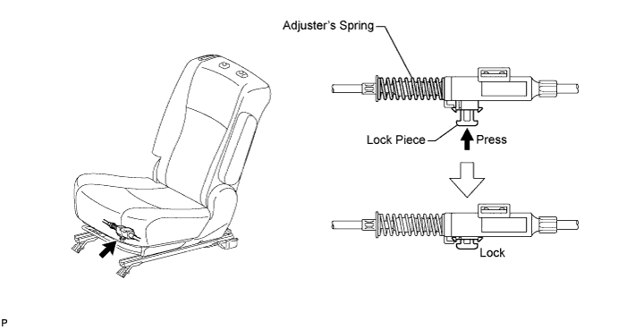
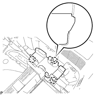
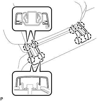
Pull up the adjuster's lock piece to lock it as shown in the illustration.
Note:When pressing the lock piece, make sure the adjuster's spring is not compress.
-
- Click here
INSPECT REAR SEAT SLIDE ADJUSTER LOCK (for RH Side)
-
Check that the left and right adjusters lock simultaneously when sliding the seat.
-
If the left and right adjusters do not lock simultaneously, adjust by loosening the bolts securing the seat.
-
- Click here
INSTALL REAR SEAT LEG SIDE COVER RH
-
Engage the clip.
-
Engage the 3 claws and install the rear seat leg side cover.
-
- Click here
INSTALL REAR INNER TRACK BRACKET COVER RH
-
Engage the 4 claws and install the rear inner track bracket cover.
-
- Click here
INSTALL REAR OUTER TRACK BRACKET COVER RH
-
Engage the 4 claws and install the rear outer track bracket cover.
-
- Click here
INSTALL SEAT TRACK BRACKET COVER RH
-
Engage the 8 claws and install the 2 seat track bracket covers.
-
- Click here
INSTALL REAR SEAT HEADREST ASSEMBLY (for RH Side)
- Click here
INSTALL REAR NO. 1 SEAT ASSEMBLY LH
-
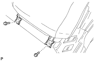
Temporarily install the 2 bolts on the front side of the seat.
-
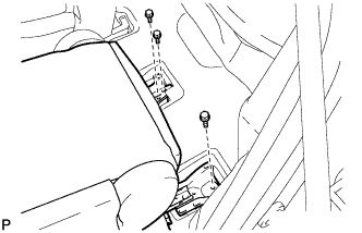
Temporarily install the 3 bolts on the rear side of the seat.
-
Install the rear No. 1 seat assembly with the 5 bolts.
37 N*m 377 kgf*cm 27 ft.*lbf
-
- Click here
CONNECT REAR NO. 1 SEAT LOCK CABLE ASSEMBLY LH (w/ Remote Folding Function)
-
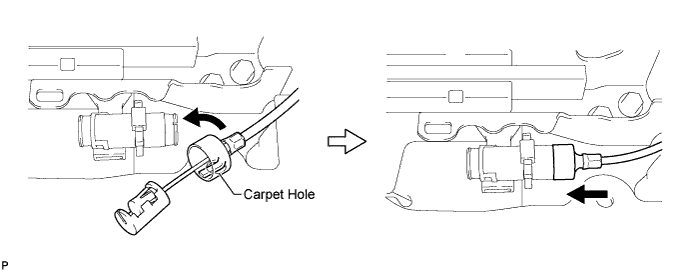
Remove the rear seat reclining control cable from the carpet hole.
-
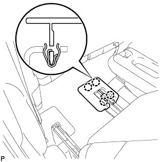
Connect the rear seat reclining control cable as shown in the illustration.
-
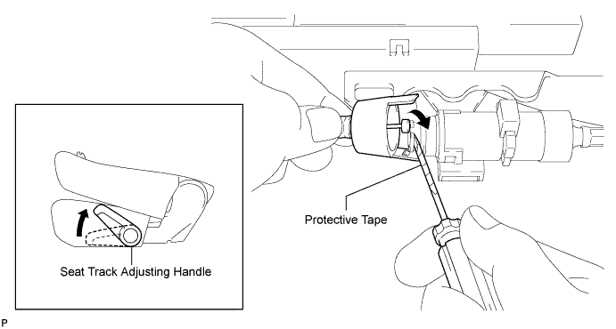
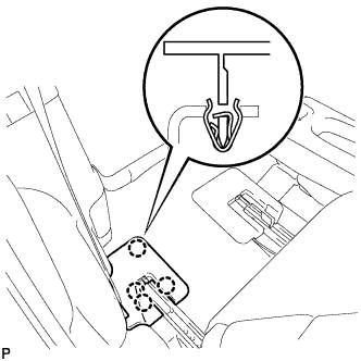
Connect the rear No. 1 seat lock cable assembly as shown in the illustration.
-
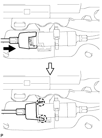
Engage the 2 claws and connect the rear No. 1 seat lock cable assembly as shown in the illustration.
-
Return the seatback to the upright position.
-
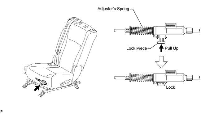
Pull up the adjuster's lock piece to lock it as shown in the illustration.
Note:When pressing the lock piece, make sure the adjuster's spring is not compress.
-
- Click here
INSPECT REAR SEAT SLIDE ADJUSTER LOCK (for LH Side)
-
Check that the left and right adjusters lock simultaneously when sliding the seat.
-
If the left and right adjusters do not lock simultaneously, adjust by loosening the bolts securing the seat.
-
- Click here
INSTALL REAR SEAT LEG SIDE COVER LH
-
Engage the clip.
-
Engage the 3 claws and install the rear seat leg side cover.
-
- Click here
INSTALL REAR INNER TRACK BRACKET COVER LH
-
Engage the 4 claws and install the rear inner track bracket cover.
-
- Click here
INSTALL REAR OUTER TRACK BRACKET COVER LH
-
Engage the 4 claws and install the rear outer track bracket cover.
-
- Click here
INSTALL SEAT TRACK BRACKET COVER LH
-
Engage the 8 claws and install the 2 rear seat track bracket covers.
-
- Click here
INSTALL REAR SEAT HEADREST ASSEMBLY (for LH Side)
- Click here
INSTALL REAR CENTER SEAT ASSEMBLY
- Click here
CONNECT CABLE TO NEGATIVE BATTERY TERMINAL
Note:When disconnecting the cable, some systems need to be initialized after the cable is reconnected (See PageClick here).
- Click here
INSPECT SRS WARNING LIGHT
-
Inspect the SRS warning light (Click here).
-