FUEL INJECTOR REMOVAL
-
DISCHARGE FUEL SYSTEM PRESSURE
Tech Tips
-
DISCONNECT CABLE FROM NEGATIVE BATTERY TERMINAL
Note
When disconnecting the cable, some systems need to be initialized after the cable is reconnected Click here.
-
REMOVE ENGINE UNDER COVER ASSEMBLY
-

Remove the 2 bolts and engine under cover assembly RR.
-

Remove the 2 bolts, 2 screws, 5 clips and engine under cover assembly.
-
-
REMOVE NO. 1 ENGINE UNDER COVER
-
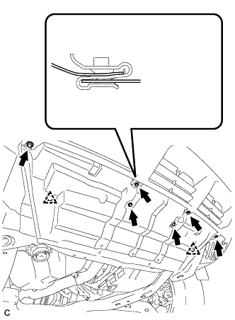
Remove the 6 bolts, 2 clips and No. 1 engine under cover.
-
-
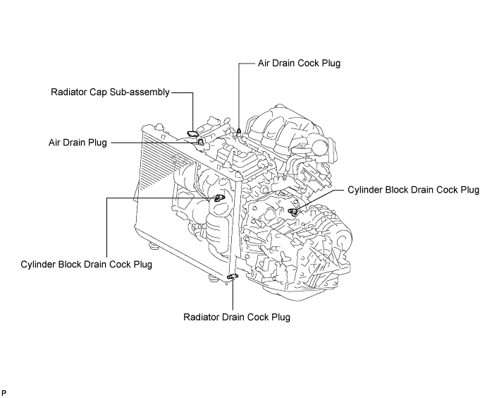
DRAIN ENGINE COOLANT
-
Loosen the radiator drain cock plug.
Tech Tips
Collect the coolant in a container and dispose of it according to the regulations in your area.
-
Remove the radiator cap sub-assembly from the radiator assembly.
Note
Do not remove the radiator cap sub-assembly while the engine and radiator are still hot. Pressurized, hot engine coolant and steam may be released and cause serious burns.
-
Loosen the 2 cylinder block drain cock plugs.
-
-
REMOVE FRONT WIPER ARM AND BLADE ASSEMBLY LH
-
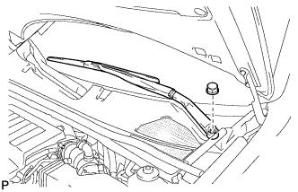
Remove the nut, and the front wiper arm and blade assembly LH.
-
-
REMOVE FRONT WIPER ARM AND BLADE ASSEMBLY RH
-
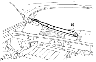
Remove the nut, and the front wiper arm and blade assembly RH.
-
-
REMOVE COWL TOP VENTILATOR LOUVER SUB-ASSEMBLY
-
Disengage the 2 claws and disconnect the front fender to cowl side seal LH.
-
Disengage the 2 claws and disconnect the front fender to cowl side seal RH.
-
Remove the 2 clips.
-
Disengage the 20 claws and remove the cowl top ventilator louver sub-assembly.
-
-
REMOVE WINDSHIELD WIPER MOTOR AND LINK ASSEMBLY
-
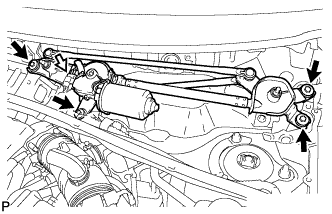
Disconnect the connector.
-
Remove the 4 bolts, and the windshield wiper motor and link assembly.
-
-
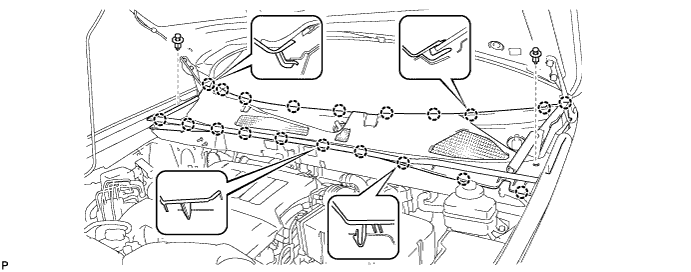
REMOVE OUTER COWL TOP PANEL SUB-ASSEMBLY
-
Disengage the 4 clamps and separate the wiper wire harness from the outer cowl top panel sub-assembly.
-
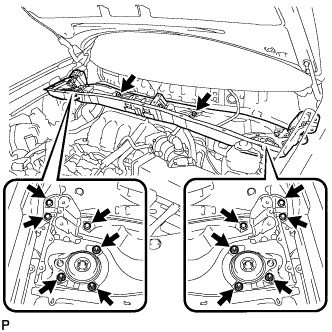
Remove the 8 bolts, 6 nuts, and the outer cowl top panel sub-assembly.
-
-
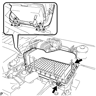
REMOVE V-BANK COVER SUB-ASSEMBLY
-
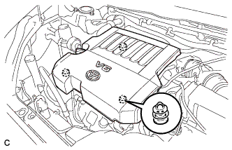
Hold the front of the V-bank cover sub-assembly and raise it to disengage the 2 clips on the front of the V-bank cover sub-assembly. Continue rising the V-bank cover sub-assembly to disengage the clip on the rear of the V-bank cover sub-assembly and remove the V-bank cover sub-assembly.
Note
Attempting to disengage both front and rear clips at the same time may cause the V-bank cover sub-assembly to break.
-
-
REMOVE AIR CLEANER CAP SUB-ASSEMBLY
-
Disconnect the 3 vacuum hoses.
-
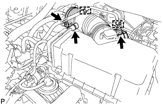
Loosen the No. 1 air cleaner hose clamp.
-
Disconnect the hose clamps and No. 2 ventilation hose.
-
Disconnect the mass air flow meter connector.
-
Release the 2 clips, and remove the 2 bolts.
-
Remove the air cleaner cap sub-assembly and air cleaner filter element.
-
-
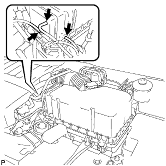
DISCONNECT ENGINE ROOM MAIN WIRE
-
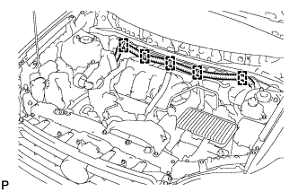
Disconnect the 5 harness clamps.
-
-
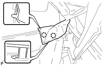
REMOVE THROTTLE BODY BRACKET
-
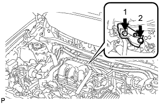
Remove the 2 bolts in the order shown in the illustration and remove the throttle body bracket.
-
-
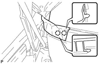
REMOVE NO. 1 SURGE TANK STAY
-
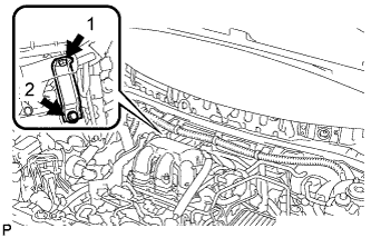
Remove the 2 bolts in the order shown in the illustration and remove the No. 1 surge tank stay.
-
-
REMOVE INTAKE AIR SURGE TANK ASSEMBLY
-
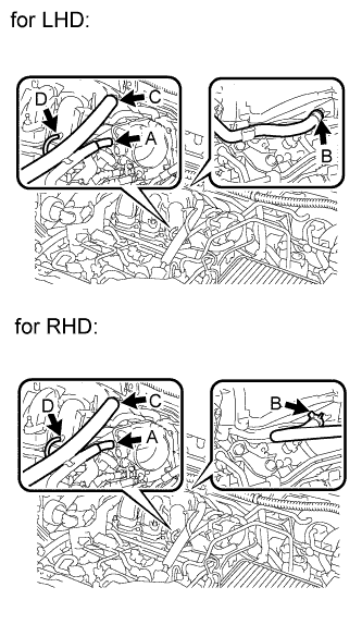
Disconnect the 4 hoses.
Tech Tips
-
A: vapor feed hose
-
B: union to check valve hose
-
C: No. 1 ventilation hose
-
D: vacuum hose
-
-
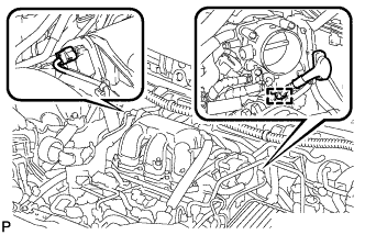
Disconnect the throttle body connector and clamp.
-
Disconnect the connector.
-
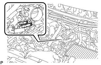
Disconnect the 2 water by-pass hoses from the throttle body.
-
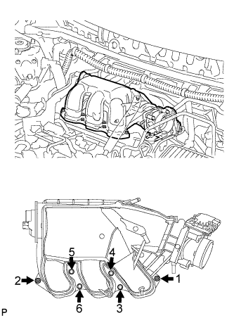
Remove the 4 bolts with a 5 mm socket hexagon wrench and 2 nuts in the order shown in the illustration.
-
Remove the gasket from the intake air surge tank.
-
-
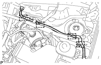
DISCONNECT FUEL TUBE SUB-ASSEMBLY
-
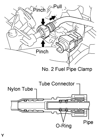
Remove the No. 2 fuel pipe clamp.
-
Pinch the tube connector and pull out the fuel pipe.
Note
-
Check that there is no dirt or other foreign objects around the connector before disconnecting it. Clean the connector as necessary.
-
It is necessary to prevent dirt or foreign objects from entering the quick connector. If dirt or foreign objects enter the connector, the O-rings may not seal properly.
-
Only disconnect the quick connector by hand.
-
Do not bend, kink or twist the nylon tubes. Protect the connector by covering it with a plastic bag.
-
If the pipe and the connector are stuck, carefully try wiggling or pushing and pulling on the connector to release it. Pull the connector off the pipe carefully.
-
-
-
REMOVE FUEL DELIVERY PIPE SUB-ASSEMBLY
-
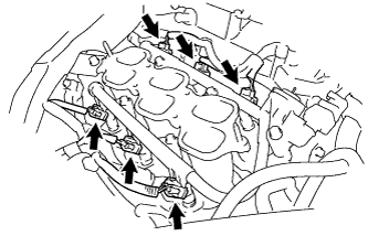
Disconnect the 6 fuel injector connectors.
-
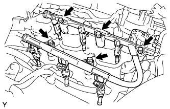
Remove the 5 bolts and fuel delivery pipe sub-assembly together with the 6 fuel injectors.
Note
Be careful not to drop the fuel injectors when removing the fuel delivery pipe sub-assembly.
-

Remove the 6 injector vibration insulators from the intake manifold.
-
-
REMOVE FUEL INJECTOR ASSEMBLY
-
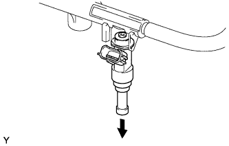
Pull out the fuel injectors from the fuel delivery pipe.
Note
If the injectors are to be reused, reinstall them to the same cylinder they came from.
-
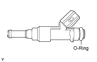
Remove the 6 O-rings from the injectors.
-