- Click here
INSPECT CONNECTING ROD THRUST CLEARANCE
-
Install the connecting rod cap (Click here).
-
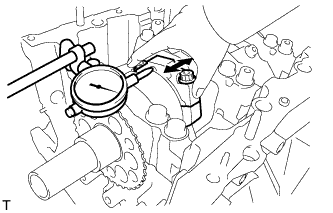
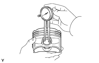
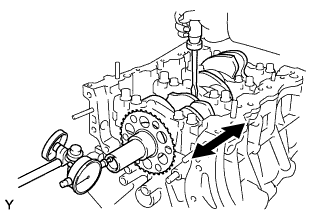
Using a dial indicator, measure the thrust clearance while moving the connecting rod back and forth.
Standard thrust clearance 0.15 to 0.40 mm (0.0059 to 0.0157 in.) Maximum thrust clearance 0.50 mm (0.020 in.) If the thrust clearance is greater than the maximum, replace the connecting rod assembly. If necessary, replace the crankshaft.
-
- Click here
INSPECT CONNECTING ROD OIL CLEARANCE
-
Clean the crank pin and bearing.
-
Check the crank pin and bearing for pitting and scratches.
-
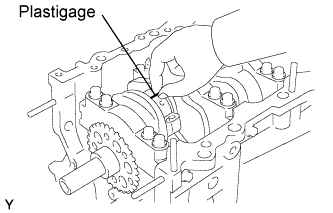
Lay a strip of Plastigage on the crank pin.
-
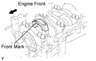
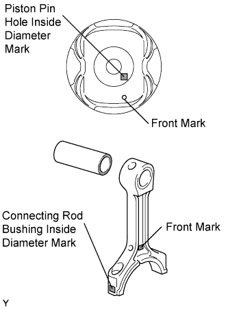
Ensure that the front mark of the connecting rod cap is facing forward.
-
Install the connecting rod cap (Click here).
Note:Do not turn the crankshaft.
-
Remove the 2 bolts and connecting rod cap (Click here).
-
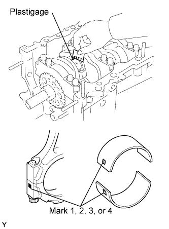
Measure the Plastigage at its widest point.
Standard oil clearance 0.045 to 0.067 mm (0.0018 to 0.0026 in.) Maximum oil clearance 0.070 mm (0.0028 in.) If the oil clearance is greater than the maximum, replace the connecting rod bearings. If necessary, inspect the crankshaft.
Tip:If replacing a bearing, replace it with one that has the same number as its respective connecting rod cap. Each bearing's standard thickness is indicated by a number (1, 2, 3 or 4) marked on its surface.
Connecting rod diameter Mark Diameter 1 56.000 to 56.006 mm (2.2047 to 2.2050 in.) 2 56.007 to 56.012 mm (2.2050 to 2.2052 in.) 3 56.013 to 56.018 mm (2.2052 to 2.2054 in.) 4 56.019 to 56.024 mm (2.2055 to 2.2057 in.) Connecting rod bearing center wall thickness Mark Thickness 1 1.481 to 1.484 mm (0.0583 to 0.0584 in.) 2 1.484 to 1.487 mm (0.0584 to 0.0585 in.) 3 1.487 to 1.490 mm (0.0585 to 0.0587 in.) 4 1.490 to 1.493 mm (0.0587 to 0.0588 in.) Standard crankshaft pin diameter 52.992 to 53.000 mm (2.0863 to 2.0866 in.) Note:Completely remove the Plastigage after the measurement.
-
- Click here
INSPECT CYLINDER BLOCK FOR WARPAGE
-
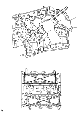
Using a precision straight edge and feeler gauge, measure the warpage of the contact surface of the cylinder head gasket.
Maximum warpage 0.07 mm (0.0028 in.) If the warpage is greater than the maximum, replace the cylinder block sub-assembly.
-
- Click here
INSPECT CYLINDER BORE
-
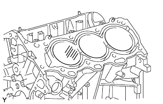
Visually check the cylinder for vertical scratches.
If deep scratches are present, rebore all the 6 cylinders. If necessary, replace the cylinder block.
-
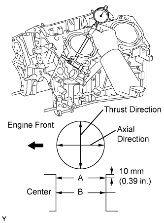
Using a cylinder gauge, measure the cylinder bore diameter at positions A and B in the thrust and axial directions.
Standard diameter 94.000 to 94.012 mm (3.7008 to 3.7013 in.) Maximum diameter 94.200 mm (3.7087 in.) If the average diameter of 4 positions is greater than the maximum, replace the cylinder block sub-assembly.
-
- Click here
INSPECT PISTON SUB-ASSEMBLY WITH PIN
-
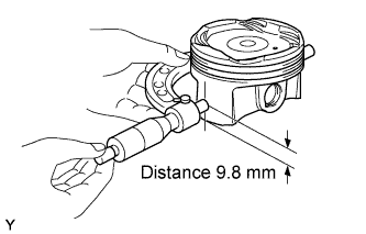
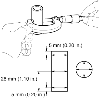
Using a micrometer, measure the piston diameter at right angles to the piston center line where the distance from the piston end is as specified.
Distance 9.8 mm (0.3858 in.) Standard diameter 93.960 to 93.980 mm (3.6992 to 3.7000 in.) Minimum diameter 93.830 mm (3.6941 in.)
-
- Click here
INSPECT PISTON OIL CLEARANCE
-
Measure the cylinder bore diameter in the thrust directions.
-
Subtract the piston diameter measurement from the cylinder bore diameter measurement.
Standard oil clearance 0.020 to 0.052 mm (0.0008 to 0.0020 in.) Maximum oil clearance 0.060 mm (0.0024 in.) If the oil clearance is greater than the maximum, replace all the pistons. If necessary, replace the cylinder block sub-assembly.
-
- Click here
INSPECT RING GROOVE CLEARANCE
-
Using a feeler gauge, measure the clearance between a new piston ring and the wall of the ring groove.
Ring groove clearance Item Clearance No. 1 0.020 to 0.070 mm (0.0008 to 0.0028 in.) No. 2 0.020 to 0.060 mm (0.0008 to 0.0024 in.) Oil 0.070 to 0.150 mm (0.0028 to 0.0059 in.) If the clearance is not as specified, replace the piston.
-
- Click here
INSPECT PISTON PIN OIL CLEARANCE
-
Using a caliper gauge, measure the inside diameter of the piston pin hole.
Piston pin hole inside diameter Mark Diameter A 22.001 to 22.004 mm (0.8662 to 0.8663 in.) B 22.004 to 22.007 mm (0.8663 to 0.8664 in.) C 22.007 to 22.010 mm (0.8664 to 0.8665 in.) -
Using a micrometer, measure the piston pin diameter.
Piston pin diameter Mark Diameter A 21.997 to 22.000 mm (0.8660 to 0.8661 in.) B 22.000 to 22.003 mm (0.8661 to 0.8663 in.) C 22.003 to 22.006 mm (0.8663 to 0.8664 in.) -
Subtract the piston pin diameter measurement from the piston pin hole diameter measurement.
Standard oil clearance 0.001 to 0.007 mm (0.00004 to 0.00028 in.) Maximum oil clearance 0.015 mm (0.0006 in.) If the oil clearance is greater than the maximum, replace the piston and piston pin as a set.
-
Using a caliper gauge, measure the inside diameter of the connecting rod bushing.
Bushing inside diameter Mark Diameter A 22.005 to 22.008 mm (0.8663 to 0.8665 in.) B 22.009 to 22.011 mm (0.8665 to 0.8666 in.) C 22.012 to 22.014 mm (0.8666 to 0.8667 in.) -
Subtract the piston pin diameter measurement from the bushing inside diameter measurement.
Standard oil clearance 0.005 to 0.011 mm (0.0002 to 0.0004 in.) Maximum oil clearance 0.030 mm (0.0012 in.) If the oil clearance is greater than the maximum, replace the bushing. If necessary, replace the connecting rod and piston pin as a set.
-
- Click here
INSPECT PISTON RING END GAP
-
Insert the piston ring into the cylinder bore.
-
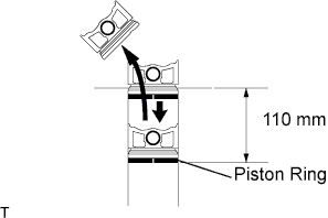
Using a piston, push the piston ring slightly beyond the bottom of the ring travel, 110 mm (4.33 in.) from the top of the cylinder block sub-assembly.
-
Using a feeler gauge, measure the end gap.
Standard end gap Item End Gap No. 1 0.25 to 0.35 mm (0.0098 to 0.0138 in.) No. 2 0.50 to 0.60 mm (0.0197 to 0.0236 in.) Oil 0.10 to 0.40 mm (0.0039 to 0.0157 in.) Maximum end gap Item End Gap No. 1 0.50 mm (0.0197 in.) No. 2 0.85 mm (0.0335 in.) Oil 0.60 mm (0.0236 in.) If the end gap is greater than the maximum, replace the piston ring. If the end gap is greater than the maximum even with a new piston ring, rebore all the 6 cylinders or replace the cylinder block sub-assembly.
-
- Click here
INSPECT CRANKSHAFT THRUST CLEARANCE
-
Install the crankshaft bearing cap (Click here).
-
Using a dial indicator, measure the thrust clearance while prying the crankshaft back and forth with a screwdriver.
Standard thrust clearance 0.04 to 0.24 mm (0.0016 to 0.0094 in.) Maximum thrust clearance 0.30 mm (0.0118 in.) If the thrust clearance is greater than the maximum, replace the thrust washers as a set. If necessary, replace the crankshaft.
Thrust washer thickness 2.43 to 2.48 mm (0.0957 to 0.0976 in.)
-
- Click here
INSPECT CONNECTING ROD SUB-ASSEMBLY
-
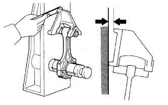
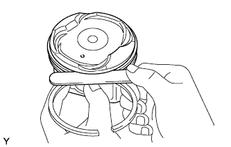
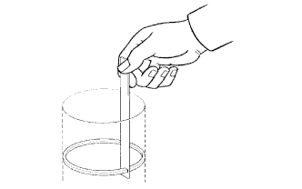
Using a rod aligner and feeler gauge, check the connecting rod alignment.
-
Check for out-of-alignment.
Maximum out-of-alignment 0.05 mm (0.0020 in.) per 100 mm (3.94 in.) If the out-of-alignment is greater than the maximum, replace the connecting rod sub-assembly.
-
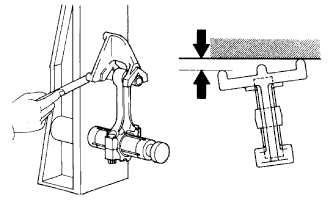
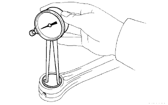
Check for twist.
Maximum twist 0.15 mm (0.0059 in.) per 100 mm (3.94 in.) If the twist is greater than the maximum, replace the connecting rod sub-assembly.
-
-
- Click here
INSPECT CONNECTING ROD BOLT
-
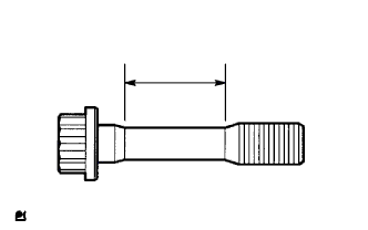
Using vernier calipers, measure the tension portion diameter of the bolt.
Standard diameter 7.2 to 7.3 mm (0.284 to 0.287 in.) Minimum diameter 7.0 mm (0.276 in.) If the diameter is less than the minimum, replace the bolt.
-
- Click here
INSPECT CRANKSHAFT
-
Inspect for runout.
-
Clean the crank journal.
-
Place the crankshaft on V-blocks.
-
Using a dial indicator, measure the runout at the center journal.
Maximum runout 0.06 mm (0.0024 in.) If the runout is greater than the maximum, replace the crankshaft.
-
-
Inspect the main journals.
-
Using a micrometer, measure the diameter of each main journal.
Standard journal diameter 60.988 to 61.000 mm (2.4011 to 2.4016 in.) If the diameter is not as specified, check the oil clearance. If necessary, replace the crankshaft.
-
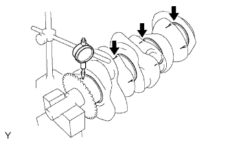
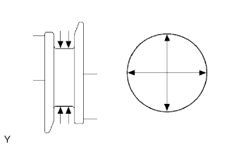
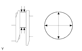
Check each main journal for taper and out-of-round as shown in the illustration.
Maximum taper and out-of-round 0.02 mm (0.0008 in.) If the taper and out-of-round is greater than the maximum, replace the crankshaft.
-
-
Inspect the crank pin.
-
Using a micrometer, measure the diameter of each crank pin.
Crank pin diameter 52.992 to 53.000 mm (2.0863 to 2.0866 in.) If the diameter is not as specified, check the oil clearance. If necessary, replace the crankshaft.
-
Check each crank pin for taper and out-of-round as shown in the illustration.
Maximum taper and out-of-round 0.02 mm (0.0008 in.) If the taper and out-of-round is greater than the maximum, replace the crankshaft.
-
-
- Click here
INSPECT CRANKSHAFT OIL CLEARANCE
-
Check the crank journal and crankshaft bearing for pitting and scratches.
-
Install the crankshaft bearing (Click here).
-
Place the crankshaft on the cylinder block.
-
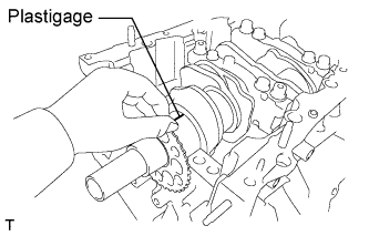
Lay a strip of Plastigage across each journal.
-
Examine the front marks and numbers to install the crankshaft bearing caps on the cylinder block.
Tip:A number is marked on each main bearing cap to indicate the installation position.
-
Install the main bearing cap (Click here).
Note:Do not turn the crankshaft.
-
Remove the main bearing caps (Click here).
-
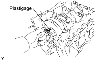
Measure the Plastigage at its widest point.
Standard oil clearance 0.026 to 0.047 mm (0.0010 to 0.0019 in.) Maximum oil clearance 0.050 mm (0.0020 in.) If the oil clearance is greater than the maximum, replace the bearings. If necessary, replace the crankshaft.
Note:Completely remove the Plastigage after the measurement.
-
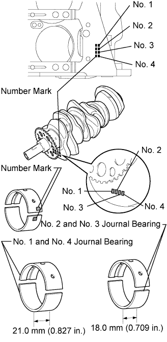
If replacing a bearing, replace it with one having the same number. If the number of the bearing cannot be determined, select the correct bearing by adding together the numbers imprinted on the cylinder block and crankshaft, then refer to the table below for the appropriate bearing number. There are 5 sizes of standard bearings, marked "1", "2", "3", "4" and "5" accordingly.
Table 1. Journal bearings: Cylinder block + Crankshaft 0 - 5 6 - 11 12 - 17 18 - 23 24 - 28 Bearing to be used "1" "2" "3" "4" "5" Tip:EXAMPLE: Cylinder block "11" + Crankshaft "06" = Total number 17 (Use bearing "3")
Crankshaft main journal diameter Mark Diameter "00" 60.999 to 61.000 mm (2.4015 to 2.4016 in.) "01" 60.998 to 60.999 mm (2.4015 to 2.4015 in.) "02" 60.997 to 60.998 mm (2.4015 to 2.4015 in.) "03" 60.996 to 60.997 mm (2.4014 to 2.4015 in.) "04" 60.995 to 60.996 mm (2.4014 to 2.4014 in.) "05" 60.994 to 60.995 mm (2.4013 to 2.4014 in.) "06" 60.993 to 60.994 mm (2.4013 to 2.4013 in.) "07" 60.992 to 60.993 mm (2.4013 to 2.4013 in.) "08" 60.991 to 60.992 mm (2.4012 to 2.4013 in.) "09" 60.990 to 60.991 mm (2.4012 to 2.4012 in.) "10" 60.989 to 60.990 mm (2.4011 to 2.4012 in.) "11" 60.988 to 60.989 mm (2.4011 to 2.4011 in.) Standard upper bearing center wall thickness (No. 1 and No. 4 journal) Mark Thickness "1" 2.500 to 2.503 mm (0.0984 to 0.0985 in.) "2" 2.503 to 2.506 mm (0.0985 to 0.0987 in.) "3" 2.506 to 2.509 mm (0.0987 to 0.0988 in.) "4" 2.509 to 2.512 mm (0.0988 to 0.0989 in.) "5" 2.512 to 2.515 mm (0.0989 to 0.0990 in.) Standard lower bearing center wall thickness (No. 1 and No. 4 journal) Mark Thickness "1" 2.478 to 2.481 mm (0.0976 to 0.0977 in.) "2" 2.481 to 2.484 mm (0.0977 to 0.0978 in.) "3" 2.484 to 2.487 mm (0.0978 to 0.0979 in.) "4" 2.487 to 2.490 mm (0.0979 to 0.0980 in.) "5" 2.490 to 2.493 mm (0.0980 to 0.0981 in.) Standard upper bearing center wall thickness (No. 2 and No. 3 journal) Mark Thickness "1" 2.478 to 2.481 mm (0.0976 to 0.0977 in.) "2" 2.481 to 2.484 mm (0.0977 to 0.0978 in.) "3" 2.484 to 2.487 mm (0.0978 to 0.0979 in.) "4" 2.487 to 2.490 mm (0.0979 to 0.0980 in.) "5" 2.490 to 2.493 mm (0.0980 to 0.0981 in.) Standard lower bearing center wall thickness (No. 2 and No. 3 journal) Mark Thickness "1" 2.500 to 2.503 mm (0.0984 to 0.0985 in.) "2" 2.503 to 2.506 mm (0.0985 to 0.0987 in.) "3" 2.506 to 2.509 mm (0.0987 to 0.0988 in.) "4" 2.509 to 2.512 mm (0.0988 to 0.0989 in.) "5" 2.512 to 2.515 mm (0.0989 to 0.0990 in.)
-
- Click here
INSPECT CRANKSHAFT BEARING CAP SET BOLT
-
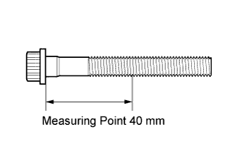
Using vernier calipers, measure the minimum diameter of the compressed thread at the measuring point.
Standard diameter 10.8 to 11.0 mm (0.4252 to 0.4331 in.) Minimum diameter 10.7 mm (0.4213 in.) Measuring Point 40 mm (1.57 in.) If the diameter is less than the minimum, replace the bolt.
-
- Click here
INSPECT NO. 1 OIL NOZZLE SUB-ASSEMBLY
-
Check the oil nozzles for damage or clogs.
Tip:If there is damage or clogs, replace the oil nozzle.
-