ENGINE ON-VEHICLE INSPECTION
-
INSPECT ENGINE COOLANT
-
Inspect the engine coolant Click here.
-
-
INSPECT ENGINE OIL
-
Inspect the engine oil Click here.
-
-
INSPECT BATTERY
-
Inspect the battery Click here.
-
-
INSPECT AIR CLEANER FILTER ELEMENT SUB-ASSEMBLY
-
Remove the air cleaner filter element sub-assembly.
-
Visually check that there is no dirt, blockage, and/or damage to the air cleaner filter element sub-assembly.
Tech Tips
-
If there is any dirt or a blockage in the air cleaner filter element sub-assembly, clean it with compressed air.
-
If any dirt or a blockage remains even after cleaning the air cleaner filter element sub-assembly with compressed air, replace it.
-
-
-
INSPECT SPARK PLUG
-
Inspect the spark plugs Click here.
-
-
INSPECT VALVE LASH ADJUSTER NOISE
-
Rev up the engine several times. Check that the engine does not emit unusual noises.
If unusual noises occur, warm up the engine and idle it for over 30 minutes. Then perform the preceding inspection.
Tech Tips
If any defects or problems are found during the preceding inspection, perform lash adjuster inspection Click here.
-
-
INSPECT IGNITION TIMING
-
When using the intelligent tester:
Check the ignition timing.
-
Connect the intelligent tester to the DLC3.
-
Warm up the engine.
-
Turn the tester on.
-
Enter the following menu items: Powertrain / Engine and ECT / Data List / IGN Advance.
-
Read the value displayed on the tester.
Ignition timing 8 to 12° BTDC at idle Tech Tips
Refer to the intelligent tester operator's manual for help when selecting the DATA LIST.
-
-
When not using the intelligent tester:
Check the ignition timing.
-
Warm up the engine.
-
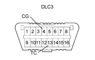
Using SST, connect terminals 13 (TC) and 4 (CG) of the DLC3.
- SST
- 09843-18040
Note
-
Confirm the terminal numbers before connecting them. Connecting the wrong terminals can damage the engine.
-
Turn off all electrical systems before connecting the terminals.
-
Perform this inspection after the cooling fan motor is turned off.
-
Remove the V-bank cover sub-assembly.
-
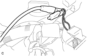
Pull out the red lead wire harness.
-
Connect the tester terminal of the timing light to the red lead wire as shown in the illustration.
Note
Use a timing light which detects the cylinder 1 ignition signal.
-
Check the ignition timing at idle.
Standard ignition timing 8 to 12° BTDC at idle Note
When checking the ignition timing, the transmission should be in the neutral position.
Tech Tips
Run the engine at 1000 to 1300 rpm for 5 seconds, and then check that the engine rpm returns to idle speed.
-
Disconnect terminals 13 (TC) and 4 (CG) of the DLC3.
-
Check the ignition timing at idle.
Standard ignition timing 7 to 24° BTDC at idle -
Confirm that the ignition timing advances immediately when the engine rpm is increased.
-
Remove the timing light from the engine.
-
-
-
INSPECT ENGINE IDLE SPEED
-
When using the intelligent tester:
Check the idle speed.
-
Connect the intelligent tester to the DLC3.
-
Warm up the engine.
-
Turn the tester on.
-
Enter the following menu items: Powertrain / Engine and ECT / Data List / Engine Speed.
-
Read the value displayed on the tester.
Idle speed 600 to 700 rpm Note
-
When checking the idle speed, the transmission should be the in neutral position.
-
Check the idle speed with the cooling fan off.
-
Switch off all accessories and air conditioning before connecting the intelligent tester.
Tech Tips
Refer to the intelligent tester operator's manual for further details.
-
-
-
When not using the intelligent tester:
Check the idle speed.
-
Warm up the engine.
-
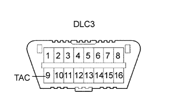
Using SST, connect the tachometer test probe to terminal 9 (TAC) of the DLC3.
- SST
- 09843-18030
-
Check the idle speed.
Standard idle speed 600 to 700 rpm
-
-
-
INSPECT COMPRESSION
-
Warm up and stop the engine.
-
Disconnect the injector connectors.
-
Remove the intake air surge tank assembly Click here.
-
Remove the 6 ignition coils.
-
Remove the 6 spark plugs.
-
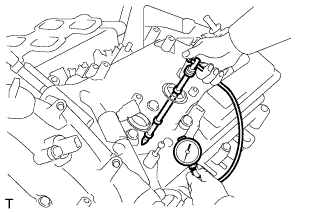
Check the cylinder compression pressure.
-
Insert a compression gauge into the spark plug hole.
-
While cranking the engine, measure the compression pressure.
Standard compression pressure 1.3 MPa (13 kgf/cm2, 189 psi) Minimum pressure 0.98 MPa (10 kgf/cm2, 142 psi) Difference between each cylinder 0.1 MPa (1.0 kgf/cm2, 15 psi) Note
-
Always use a fully charged battery to obtain an engine speed of 250 rpm or more.
-
Check the other cylinders' compression pressure in the same way.
-
This measurement must be done as quickly as possible.
-
-
If the cylinder compression is low, pour a small amount of engine oil into the cylinder through the spark plug hole and inspect again.
Tech Tips
-
If adding oil increases the compression, the piston rings and/or cylinder bore may be worn or damaged.
-
If pressure stays low, a valve may be stuck or seated improperly, or there may be leakage in the gasket.
-
-
-
Install the 6 spark plugs.
- Torque:
- 18 N*m { 184 kgf*cm, 13 ft.*lbf }
-
Install the 6 ignition coils.
- Torque:
- 10 N*m { 102 kgf*cm, 7 ft.*lbf }
-
Install the intake air surge tank assembly Click here.
-
-
INSPECT CO/HC
-
Start the engine.
-
Run the engine at 2500 rpm for approximately 180 seconds.
-
Insert the CO/HC meter testing probe at least 40 cm (1.3 ft.) into the tailpipe during idling.
-
Check CO/HC concentration at idle and/or 2500 rpm.
Tech Tips
Check regulations and restrictions in your area when performing 2 mode CO/HC concentration testing (engine check at both idle speed and at 2500 rpm).
If the CO/HC concentration does not comply with regulations, perform troubleshooting in the following order.
-
Check the air fuel ratio sensor and heated oxygen sensor operation.
-
See the following table for possible causes, and then inspect and repair if necessary.
CO HC Problem Cause Normal High Rough idle
-
Faulty ignitions:
-
Incorrect valve timing
-
Fouled, shorted or improperly gapped plugs
-
Incorrect valve clearance (valve lash adjuster)
-
Leaks in intake and exhaust valves
-
Leaks in cylinders
Low High Rough idle
(Fluctuating HC reading)
-
Vacuum leaks:
-
PCV hoses
-
Intake manifold
-
Throttle body assembly
-
Brake booster line
-
Lean mixture causing misfire
High High Rough idle
(Black smoke from exhaust)
-
Restricted air cleaner filter element sub-assembly
-
Plugged PCV valve
-
Faulty SFI system:
-
Faulty fuel pressure regulator
-
Defective engine coolant temperature sensor
-
Defective mass air flow meter
-
Faulty ECM
-
Faulty injector assemblies
-
Faulty throttle position sensor (built in throttle body assembly)
-
-
-