AIR FUEL RATIO SENSOR INSTALLATION
-
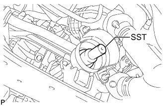
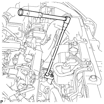
INSTALL AIR FUEL RATIO SENSOR NO.2 (for Bank 1 Sensor 1)
-
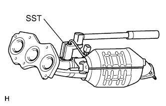
Using SST, install the air fuel ratio sensor to the exhaust manifold sub-assembly RH.
- SST
- 09224-00010
- Torque:
- 40 N*m { 408 kgf*cm, 30 ft.*lbf, for use with SST }
- 44 N*m { 449 kgf*cm, 32 ft.*lbf, for use without SST }
Tech Tips
-
Use a torque wrench with a fulcrum length of 30 cm (11.81 in.).
-
Make sure that SST and the wrench are connected in a straight line.
-
-
INSTALL EXHAUST MANIFOLD SUB-ASSEMBLY RH
-
Install a new gasket.
-
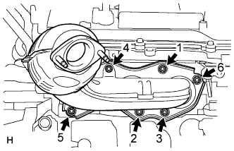
Install the exhaust manifold sub-assembly RH by tightening the 6 nuts in the order shown in the illustration.
- Torque:
- 21 N*m { 214 kgf*cm, 15 ft.*lbf }
-
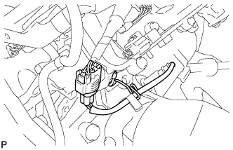
Connect the air fuel ratio sensor (for bank 1 sensor 1) connector and install the clamp.
-
-
INSTALL MANIFOLD STAY
-
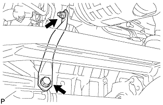
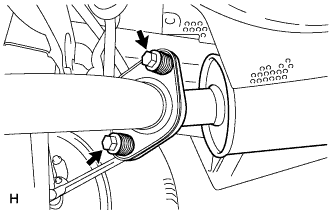
Install the manifold stay with the bolt and nut.
- Torque:
- Bolt
- 34 N*m { 347 kgf*cm, 25 ft.*lbf }
- Nut
- 35 N*m { 357 kgf*cm, 26 ft.*lbf }
-
-
INSTALL FRONT NO. 3 EXHAUST PIPE SUB-ASSEMBLY
-
Install 2 new gaskets to the front No. 3 exhaust pipe sub-assembly.
-
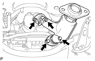
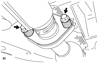
Install the front No. 3 exhaust pipe sub-assembly with 2 new nuts and the 2 bolts.
- Torque:
- 56 N*m { 571 kgf*cm, 41 ft.*lbf }
-
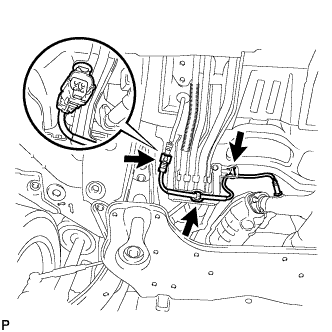
Install the 3 clamps and connect the heated oxygen sensor (for bank 1 sensor 2) connector.
-
Tighten the front exhaust pipe assembly bolt.
- Torque:
- 21 N*m { 214 kgf*cm, 15 ft.*lbf }
-
-
INSTALL CENTER EXHAUST PIPE ASSEMBLY
-
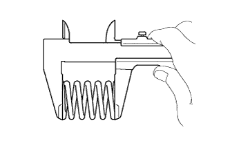
Using vernier calipers, measure the free length of the compression spring.
Minimum 41.5 mm (1.63 in.) Tech Tips
If the length is less than the minimum, replace the compression spring.
-
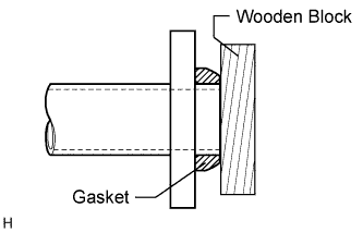
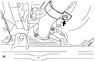
Using a plastic-faced hammer and wooden block, tap in a new gasket until its surface is flush with the front No. 3 exhaust pipe sub-assembly.
Note
-
Tap in the gasket in the correct direction.
-
Do not reuse the removed gasket.
-
Do not push in the gasket while installing the center exhaust pipe assembly.
-
-
Connect the 3 exhaust pipe supports, and install the center exhaust pipe assembly.
-
Install the 2 compression springs and 2 bolts.
- Torque:
- 48 N*m { 489 kgf*cm, 35 ft.*lbf }
-
-
INSTALL TAIL EXHAUST PIPE ASSEMBLY
-
Using vernier calipers, measure the free length of the compression spring.
Minimum 40.5 mm (1.59 in.) Tech Tips
If the length is less than the minimum, replace the compression spring.
-
Using a plastic-faced hammer and wooden block, tap in a new gasket until its surface is flush with the center exhaust pipe assembly.
Note
-
Tap in the gasket in the correct direction.
-
Do not reuse the removed gasket.
-
Do not push in the gasket while installing the tail exhaust pipe assembly.
-
-
Connect the exhaust pipe support, and install the tail exhaust pipe assembly.
-
Install the 2 compression springs and 2 bolts.
- Torque:
- 48 N*m { 489 kgf*cm, 35 ft.*lbf }
-
-
TEMPORARILY TIGHTEN PROPELLER WITH CENTER BEARING SHAFT ASSEMBLY (for 4WD)
-
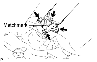
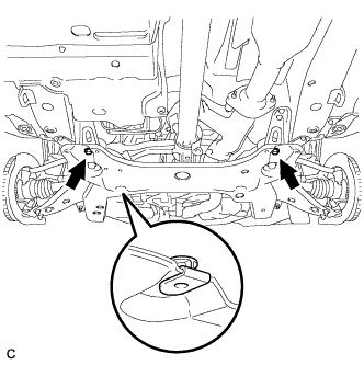
Align the matchmarks on the propeller shaft flange and differential companion flange, and connect the shaft with the 4 bolts, 4 washers and 4 nuts.
-
Remove SST from the transaxle.
-
Insert the yoke into the transaxle.
-
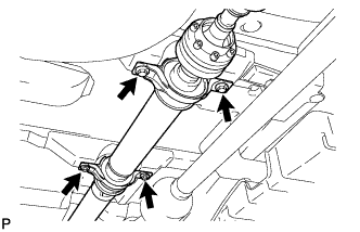
Install the 4 adjusting shims and propeller shaft with center bearing, and temporarily tighten the 4 bolts.
-
Tighten the 4 bolts.
- Torque:
- 74 N*m { 750 kgf*cm, 54 ft.*lbf }
-
-
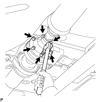
FULLY TIGHTEN PROPELLER WITH CENTER BEARING SHAFT ASSEMBLY (for 4WD)
-
Remove the piece of cloth from the joint.
-
Using a hexagon wrench (6 mm), tighten the 6 bolts.
- Torque:
- 26 N*m { 265 kgf*cm, 19 ft.*lbf }
-
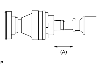
With the vehicle unloaded, adjust the dimension between the rear side of the cover and shaft as shown in the illustration.
(A) 58.0 +/- 0.5 mm (2.283 +/- 0.02 in.) -
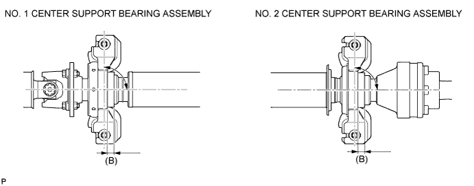
Under the same condition as above, adjust the front and rear dimensions between the edge surface of the center support bearing and the edge surface of the cushion respectively as shown, and then tighten the bolts.
- Torque:
- 37 N*m { 375 kgf*cm, 27 ft.*lbf }
(B) 12.5 +/- 1.0 mm (0.492 +/- 0.039 in.) -
Check that the center line of the bracket is at the right angle in the shaft axial direction.
-
If any vibration or noise occurs, perform joint angle check as follows and replace the adjusting shim with a proper one.
-
Turn the propeller shaft several times by hand to stabilize the center support bearings.
-
Using a jack, raise and lower the differential to stabilize the differential mounting cushion.
-
Remove the transfer dynamic damper.
-
Using SST, measure the transfer installation angle (A) and front propeller shaft installation angle (B).
- SST
- 09370-50010
No. 1 joint angle (A) - (B) = -1.3° to -3.3° -
Using SST, measure the rear propeller shaft installation angle (C) and rear differential shaft installation angle (D).
- SST
- 09370-50010
No. 2 joint angle (C) - (D) = 1.8° to 3.5° 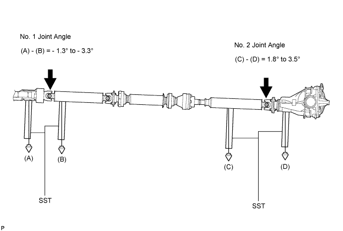
Tech Tips
If the measured angle is not within the specification, adjust it with the center support bearing adjusting shim.
Center support bearing adjusting shim thickness Thickness mm (in.) Thickness mm (in.) 3.2 (0.126) 11.0 (0.433) 4.5 (0.177) 13.5 (0.531) 6.5 (0.256) 15.5 (0.610) 9.0 (0.354) 17.5 (0.689) -
Install the transfer dynamic damper.
- Torque:
- 26 N*m { 265 kgf*cm, 19 ft.*lbf }
-
-
-
INSPECT FOR EXHAUST GAS LEAK
If exhaust gas is leaking, repair the leak. Replace damaged or worn parts as necessary.
-
INSPECT AND ADJUST TRANSFER OIL (for 4WD)
Tech Tips
-
INSTALL FRONT FLOOR COVER LH
-
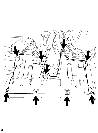
Install the 3 clamps, 6 bolts and the front floor cover LH.
-
-
INSTALL NO. 2 ENGINE UNDER COVER
-
Install the No. 2 engine under cover with the 2 bolts.
-
-
INSTALL NO. 1 ENGINE UNDER COVER
-
Install the No. 1 engine under cover with the 6 bolts and 2 clips.
-
-
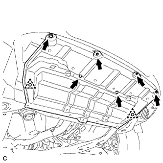
INSTALL ENGINE UNDER COVER ASSEMBLY
-

Install the engine under cover assembly with the 2 bolts, 2 screws and 5 clips.
-

Install the engine under cover assembly RR with the 2 bolts.
-
-
INSTALL AIR FUEL RATIO SENSOR (for Bank 2 Sensor 1)
-
Using SST, install the air fuel ratio sensor to the exhaust manifold sub-assembly LH.
- SST
- 09224-00010
- Torque:
- 40 N*m { 408 kgf*cm, 30 ft.*lbf, for use with SST }
- 44 N*m { 449 kgf*cm, 32 ft.*lbf, for use without SST }
Tech Tips
-
Use a torque wrench with a fulcrum length of 30 cm (11.81 in.).
-
Make sure that SST and the wrench are connected in a straight line.
-
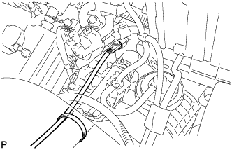
Connect the air fuel ratio sensor connector and install the clamp.
-