AIR FUEL RATIO SENSOR REMOVAL
-
REMOVE AIR FUEL RATIO SENSOR (for Bank 2 Sensor 1)
-
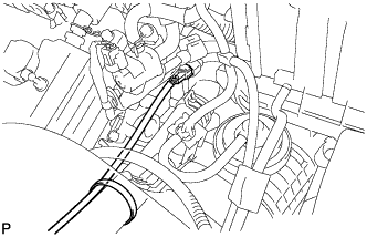
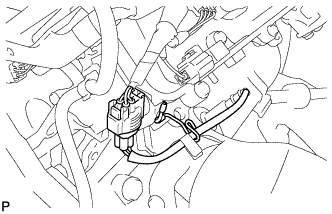
Disconnect the air fuel ratio sensor connector and remove the clamp.
-
Using SST, remove the sensor from the exhaust manifold sub-assembly LH.
- SST
- 09224-00010
-
-
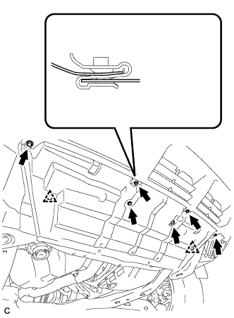
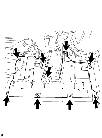
REMOVE ENGINE UNDER COVER ASSEMBLY
-

Remove the 2 bolts and engine under cover assembly RR.
-

Remove the 2 bolts, 2 screws, 5 clips and engine under cover assembly.
-
-
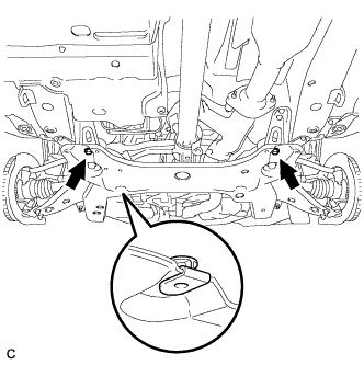
REMOVE NO. 1 ENGINE UNDER COVER
-
Remove the 6 bolts, 2 clips and No. 1 engine under cover.
-
-
REMOVE NO. 2 ENGINE UNDER COVER
-
Remove the 2 bolts and No. 2 engine under cover.
-
-
REMOVE FRONT FLOOR COVER LH
-
Remove the 3 clamps, 6 bolts and front floor cover LH.
-
-
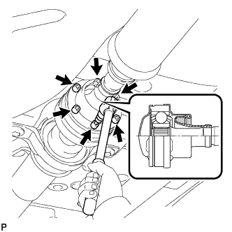
REMOVE PROPELLER WITH CENTER BEARING SHAFT ASSEMBLY (for 4WD)
-
Depress the brake pedal and hold it.
-
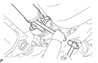
Using a hexagon wrench (6 mm), loosen the cross groove joint set bolts 1/2 turn.
Tech Tips
Put a piece of cloth or equivalent into the inside of the universal joint cover so that the boot does not touch the inside of the universal joint cover.
-
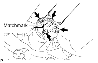
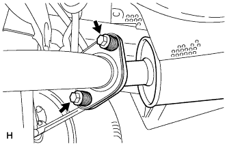
Place matchmarks on the rear propeller shaft and rear drive pinion flange sub-assembly.
-
Remove the 4 nuts, 4 bolts and 4 washers.
-
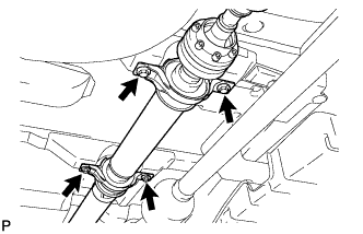
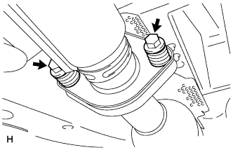
Remove the 4 bolts and 4 adjusting shims.
-
Using a brass bar and a hammer, remove the propeller shaft with center bearing shaft assembly.
-
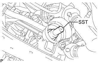
Insert SST into the transfer to prevent oil leakage.
- SST
- 09325-20010
-
-
REMOVE TAIL EXHAUST PIPE ASSEMBLY
-
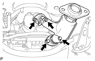
Remove the 2 bolts and 2 compression springs.
-
Disconnect the exhaust pipe support and remove the tail exhaust pipe assembly.
-
Remove the gasket from the center exhaust pipe assembly.
-
-
REMOVE CENTER EXHAUST PIPE ASSEMBLY
-
Remove the 2 bolts and 2 compression springs.
-
Disconnect the 3 exhaust pipe supports and remove the center exhaust pipe assembly.
-
Remove the gasket from the No. 3 exhaust pipe sub-assembly.
-
-
REMOVE FRONT NO. 3 EXHAUST PIPE SUB-ASSEMBLY
-
Remove the 3 clamps and disconnect the heated oxygen sensor (for bank 1 sensor 2) connector.
-
Remove the 2 bolts, 2 nuts and front No. 3 exhaust pipe sub-assembly.
-
Remove the 2 gaskets from the front No. 3 exhaust pipe sub-assembly.
-
-
REMOVE MANIFOLD STAY
-
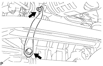
Remove the bolt, nut and manifold stay.
-
-
REMOVE EXHAUST MANIFOLD SUB-ASSEMBLY RH
-
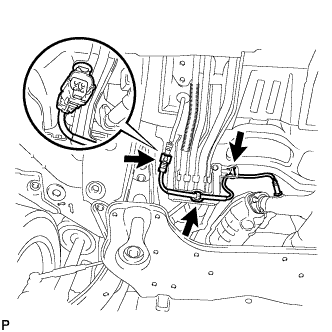
Disconnect the air fuel ratio sensor (for bank 1 sensor 1) connector and remove the clamp.
-
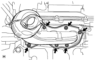
Remove the 6 nuts and exhaust manifold sub-assembly RH.
-
Remove the gasket.
-
-
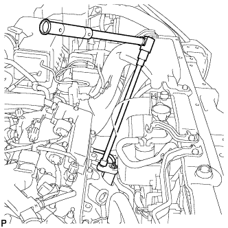
REMOVE AIR FUEL RATIO SENSOR (for Bank 1 Sensor 1)
-
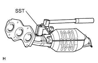
Using SST, remove the air fuel ratio sensor from the exhaust manifold sub-assembly RH.
- SST
- 09224-00010
-