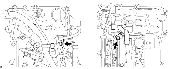
CAMSHAFT TIMING OIL CONTROL VALVE ASSEMBLY INSTALLATION
-
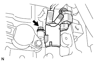
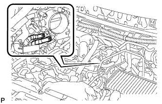
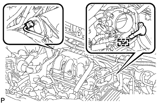
INSTALL CAMSHAFT TIMING OIL CONTROL VALVE ASSEMBLY (for Bank 2)
-
Exhaust side:
-
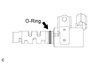
Apply a coat of engine oil to a new O-ring and install it onto the camshaft timing oil control valve assembly.
-
Install the camshaft timing oil control valve assembly with the bolt.
- Torque:
- 10 N*m { 102 kgf*cm, 7 ft.*lbf }
-
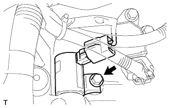
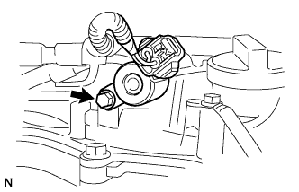
Connect the camshaft timing oil control valve assembly connector. (RHD)
-
-
Intake side:
-
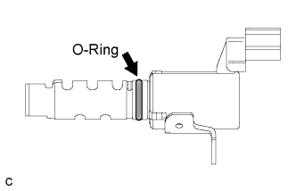
Apply a coat of engine oil to a new O-ring and install it onto the camshaft timing oil control valve assembly.
-
Install the camshaft timing oil control valve assembly with the bolt.
- Torque:
- 10 N*m { 102 kgf*cm, 7 ft.*lbf }
-
Connect the camshaft timing oil control valve assembly connector. (RHD)
-
-
-
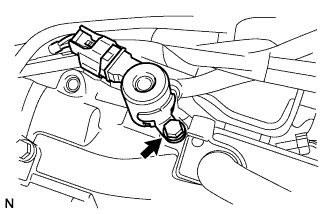
INSTALL CAMSHAFT TIMING OIL CONTROL VALVE ASSEMBLY (for Bank 1)
-
Exhaust side:
-
Apply a coat of engine oil to a new O-ring and install it onto the camshaft timing oil control valve assembly.
-
Install the camshaft timing oil control valve assembly with the bolt.
- Torque:
- 10 N*m { 102 kgf*cm, 7 ft.*lbf }
-
Connect the camshaft timing oil control valve assembly connector. (RHD)
-
-
Intake side:
-
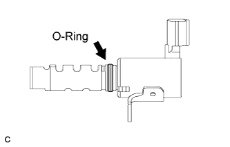
Apply a coat of engine oil to a new O-ring and install it onto the camshaft timing oil control valve assembly.
-
Install the camshaft timing oil control valve assembly with the bolt.
- Torque:
- 10 N*m { 102 kgf*cm, 7 ft.*lbf }
-
Connect the camshaft timing oil control valve assembly connector. (RHD)
-
-
-
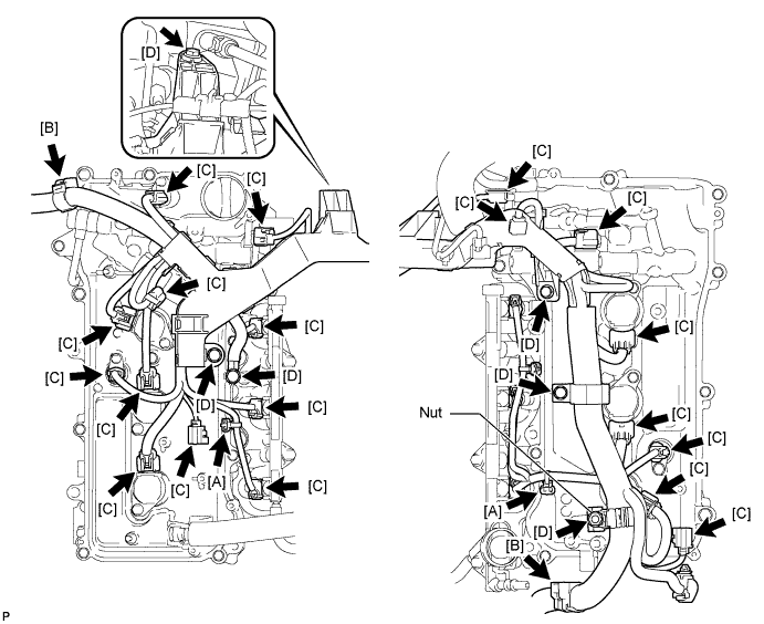
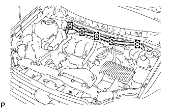
INSTALL HARNESS PROTECTOR (for LHD)
-
Connect the 2 studs [A].
-
Connect the 2 clamps [B].
-
Connect the 19 connectors [C].
-
Install the 5 bolts and nuts [D].
- Torque:
- 8.3 N*m { 84 kgf*cm, 73 in.*lbf }
-
-
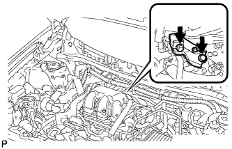
INSTALL HARNESS CLAMP BRACKET (for RHD)
-
Install the 2 bolts and harness clamp brackets.
- Torque:
- 8.3 N*m { 84 kgf*cm, 73 in.*lbf }
-
-
TEMPORARILY INSTALL NO. 1 SURGE TANK STAY
Note
DO NOT apply oil to the bolts listed below:
Tightening Parts No. 1 Surge Tank Stay and Intake Air Surge Tank Assembly No. 1 Surge Tank Stay and Cylinder Head Cover RH
-
Temporarily install the intake air surge tank assembly with 3 new gaskets on the intake manifold.
Note
Do not allow the gaskets to slip out of place during installation.
-
Temporarily install the No. 1 surge tank stay with the 2 bolts.
-
-
TEMPORARILY INSTALL THROTTLE BODY BRACKET
Note
DO NOT apply oil to the bolts listed below:
Tightening Parts Throttle body bracket and Intake Air Surge Tank Assembly Throttle body bracket and Cylinder Head Cover RH
-
Temporarily install the throttle body bracket with the 2 bolts.
-
-
INSTALL INTAKE AIR SURGE TANK ASSEMBLY
Note
DO NOT apply oil to the bolts listed below:
Tightening Parts Intake Manifold and Intake Air Surge Tank Assembly
-
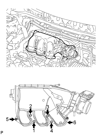
Install the surge tank with the 4 bolts and 2 nuts in the order shown in the illustration.
- Torque:
- Nut
- 16 N*m { 163 kgf*cm, 12 ft.*lbf }
- Bolt
- 18 N*m { 183 kgf*cm, 13 ft.*lbf }
Tech Tips
Use a 5 mm hexagon socket wrench to tighten the 4 bolts.
-
Connect the 2 water by-pass hoses to the throttle with motor body assembly.
-
Connect the connector.
-
Install the clamp and connect the throttle with motor body assembly connector.
-
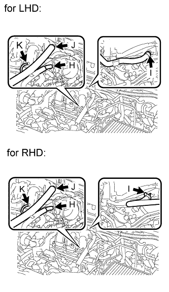
Connect the 4 hoses.
Tech Tips
-
H: vapor feed hose
-
I: union to check valve hose
-
J: No. 1 ventilation hose
-
K: vacuum hose
-
-
-
FULLY TIGHTEN NO. 1 SURGE TANK STAY
Note
DO NOT apply oil to the bolts listed below:
Tightening Parts No. 1 Surge Tank Stay and Intake Air Surge Tank Assembly No. 1 Surge Tank Stay and Cylinder Head Cover RH
-
Fully tighten the 2 bolts in the order shown in the illustration.
- Torque:
- 21 N*m { 214 kgf*cm, 15 ft.*lbf }
-
-
FULLY TIGHTEN THROTTLE BODY BRACKET
Note
DO NOT apply oil to the bolts listed below:
Tightening Parts Throttle body bracket and Intake Air Surge Tank Assembly Throttle body bracket and Cylinder Head Cover RH
-

Fully tighten the 2 bolts in the order shown in the illustration.
- Torque:
- 21 N*m { 214 kgf*cm, 15 ft.*lbf }
-
-
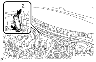
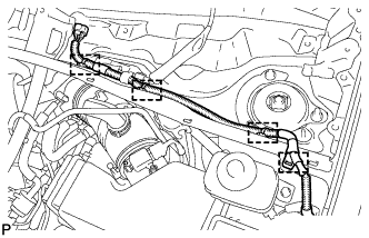
CONNECT ENGINE ROOM MAIN WIRE
-
Connect the 5 harness clamps.
-
-
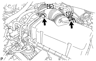
INSTALL AIR CLEANER CAP SUB-ASSEMBLY
-
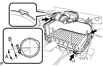
Install the air cleaner filter element, align the groove on the air cleaner hose with the throttle body alignment tab and tighten the clamp as shown in the illustration.
Tech Tips
-
A = 30°
-
B = 11 to 14 mm (0.433 in. to 0.551 in.)
-
-
Install the air cleaner cap with the 2 bolts and clips.
- Torque:
- 5.0 N*m { 51 kgf*cm, 44 in.*lbf }
-
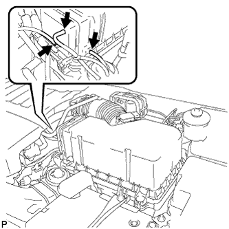
Connect the 3 vacuum hoses.
-
Connect the mass air flow meter connector.
-
Connect the No. 2 ventilation hose and fuel vapor feed hose assembly.
-
-
ADD ENGINE COOLANT
-
Tighten the radiator drain cock plug by hand.
-
Tighten the cylinder block drain cock plug. (for Bank 1)
- Torque:
- 13 N*m { 130 kgf*cm, 9 ft.*lbf }
-
Tighten the cylinder block drain cock plug. (for Bank 2, w/ Cylinder Block Drain Cock Plug)
- Torque:
- 13 N*m { 130 kgf*cm, 9 ft.*lbf }
-
Loosen the air drain cock plug on the water inlet housing.
-
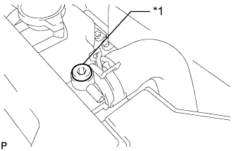
Text in Illustration *1 Air Drain Plug Loosen the air drain plug at the top of the radiator assembly 3 or 4 turns.
-
Add engine coolant to the radiator inlet opening until engine coolant overflows from the engine air drain cock hole. Then tighten the air drain cock plug.
- Torque:
- 13 N*m { 130 kgf*cm, 9 ft.*lbf }
-
Continue to add engine coolant to the radiator inlet opening until engine coolant overflows from the radiator air drain hole. Then tighten the air drain plug.
- Torque:
- 1.5 N*m { 15 kgf*cm, 13 in.*lbf }
Tech Tips
If the engine coolant level at the radiator inlet opening drops after squeezing the No. 1 radiator hose and No. 2 radiator hose, add engine coolant.
-
Slowly fill the radiator assembly with engine coolant.
Standard Capacity Condition Specified Condition w/ Rear Heater 11.7 liters (12.4 US qts, 10.3 Imp. qts) w/o Rear Heater 9.5 liters (10.1 US qts, 8.4 Imp. qts) Note
Never use water as a substitute for engine coolant.
Tech Tips
TOYOTA vehicles are filled with TOYOTA SLLC at the factory. In order to avoid damage to the engine cooling system and other technical problems, only use TOYOTA SLLC or similar high quality ethylene glycol based non-silicate, non-amine, non-nitrite, non-borate coolant with long-life hybrid organic acid technology (coolant with long-life hybrid organic acid technology is a combination of low phosphates and organic acids).
-
Slowly pour engine coolant into the radiator reservoir tank until it reaches the full line.
-
Squeeze the No. 1 radiator hose and No. 2 radiator hose several times by hand, and then check the level of the engine coolant.
If the engine coolant level is low, add engine coolant.
-
Bleed air from the cooling system.
-
Warm up the engine until the thermostat opens. While the thermostat is open, circulate the engine coolant for several minutes.
Tech Tips
The thermostat open timing can be confirmed by squeezing the No. 2 radiator hose by hand, and sensing vibrations when the engine coolant starts to flow inside the No. 2 radiator hose.
-
Maintain the engine speed at 2500 to 3000 rpm.
-
Squeeze the No. 1 radiator hose and No. 2 radiator hose several times by hand to bleed air.
CAUTION:
When squeezing the No. 1 radiator hose and No. 2 radiator hose:
-
Wear protective gloves.
-
Be careful as the No. 1 radiator hose and No. 2 radiator hose are hot.
-
Keep your hands away from the fan and No. 2 fan.
Note
-
If the coolant temperature gauge indicates an excessive temperature, turn off the engine and let it cool.
-
Make sure that the radiator reservoir tank still has some engine coolant in it.
-
If the radiator reservoir tank does not have enough engine coolant, the engine may overheat or be seriously damaged.
-
If the radiator reservoir tank does not have enough engine coolant, perform the following: 1) stop the engine, 2) wait until the engine coolant has cooled down, and 3) add engine coolant until the radiator reservoir tank is filled to the full line.
-
-
-
Stop the engine, and wait until the engine coolant cools down.
-
Add engine coolant to the full line on the radiator reservoir tank.
-
-
INSPECT FOR COOLANT LEAK
CAUTION:
Do not remove the radiator cap while the engine and radiator are still hot. Pressurized, hot engine coolant and steam may be released and cause serious burns.
Note
Before performing each inspection, turn the A/C switch off.
-
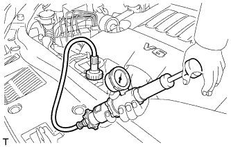
Fill the radiator with coolant and attach a radiator cap tester.
-
Warm up the engine.
-
Using the radiator cap tester, increase the pressure inside the radiator to 118 kPa (1.2 kgf/cm2, 17 psi), and check that the pressure does not drop.
If the pressure drops, check the hoses, radiator and water pump for leaks. If no external leaks are found, check the heater core, cylinder block and cylinder head.
-
-
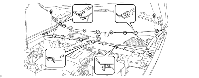
INSTALL OUTER COWL TOP PANEL SUB-ASSEMBLY
-
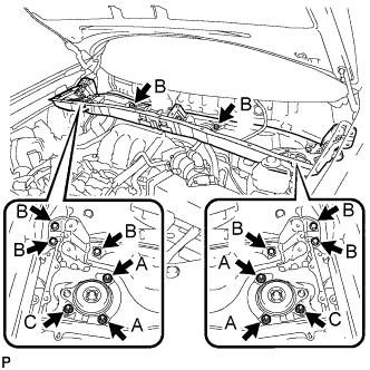
Install the outer cowl top panel sub-assembly with the 8 bolts and 6 nuts.
- Torque:
- Nut A
- 85 N*m { 866 kgf*cm, 63 ft.*lbf }
- Bolt B
- 8.8 N*m { 90 kgf*cm, 78 in.*lbf }
- Nut C
- 8.8 N*m { 90 kgf*cm, 78 in.*lbf }
-
Engage the 4 clamps.
-
-
INSTALL WINDSHIELD WIPER MOTOR AND LINK ASSEMBLY
-
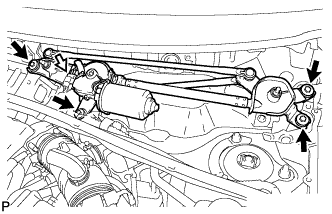
Install the windshield wiper motor and link assembly with the 4 bolts.
- Torque:
- 7.0 N*m { 71 kgf*cm, 62 in.*lbf }
-
Connect the connector.
-
-
INSTALL COWL TOP VENTILATOR LOUVER SUB-ASSEMBLY
-
Engage the 20 claws.
-
Install the cowl top ventilator louver sub-assembly with the 2 clips.
-
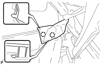
Engage the 2 claws and connect the front fender to cowl side seal LH.
-
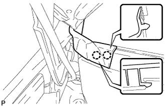
Engage the 2 claws and connect the front fender to cowl side seal RH.
-
-
INSTALL FRONT WIPER ARM AND BLADE ASSEMBLY RH
-
Operate the wiper and stop the windshield wiper motor at the automatic stop position.
-
When reinstalling:
-
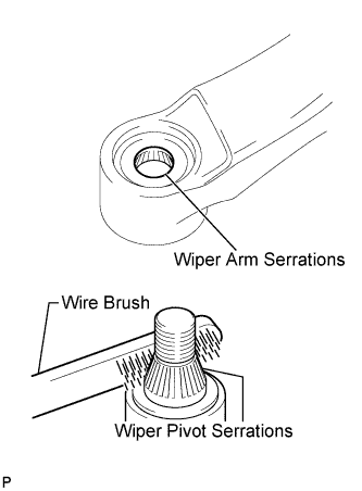
Clean the wiper arm serrations.
-
Clean the wiper pivot serrations with a wire brush.
-
-
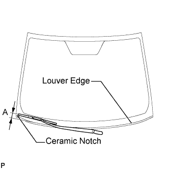
Install the front wiper arm and blade assembly RH with the nut to the position shown in the illustration.
- Torque:
- 24 N*m { 245 kgf*cm, 18 ft.*lbf }
Tech Tips
Hold the wiper arm by hand when tightening the nut.
Area Measurement A 25.6 mm (1.00 in.)
-
-
INSTALL FRONT WIPER ARM AND BLADE ASSEMBLY LH
-
Operate the wiper and stop the windshield wiper motor at the automatic stop position.
-
When reinstalling:
-
Clean the wiper arm serrations.
-
Clean the wiper pivot serrations with a wire brush.
-
-
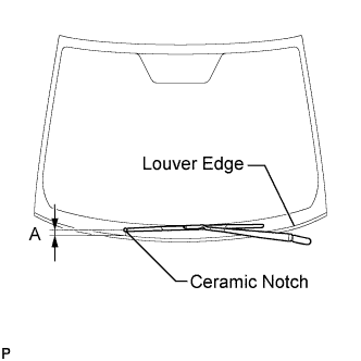
Install the front wiper arm and blade assembly LH with the nut to the position shown in the illustration.
- Torque:
- 24 N*m { 245 kgf*cm, 18 ft.*lbf }
Tech Tips
Hold the wiper arm by hand when tightening the nut.
Area Measurement A 31.9 mm (1.26 in.) -
Operate the front wipers while spraying washer fluid onto the windshield glass. Make sure that the front wipers function properly and the wipers do not come into contact with the vehicle body.
-
-
INSTALL V-BANK COVER SUB-ASSEMBLY
-
Fit the 3 retainers and install the V-bank cover.
-
-
INSTALL NO. 1 ENGINE UNDER COVER
-
Install the No. 1 engine under cover with the 6 bolts and 2 clips.
-
-
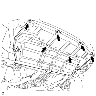
INSTALL ENGINE UNDER COVER ASSEMBLY
-

Install the engine under cover assembly with the 2 bolts, 2 screws and 5 clips.
-

Install the engine under cover assembly RR with the 2 bolts.
-