SFI SYSTEM Cranking Holding Function Circuit
DESCRIPTION
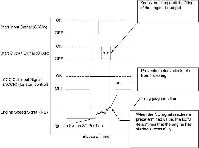
The system detects the ignition switch's starting signal (STSW) and then supplies current to the starter until the ECM judges that the engine has started successfully. The purpose is to reduce the holding time of the ignition key.
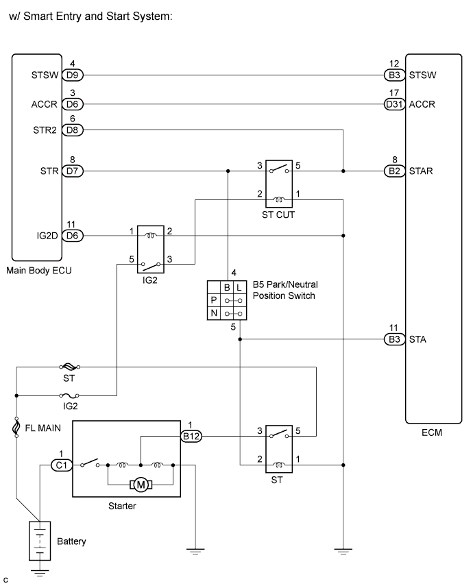
WIRING DIAGRAM
INSPECTION PROCEDURE
PROCEDURE
-
CHECK CRANKING
-
When starting the engine, check whether the starter motor starts.
OK Engine is cranking.
NG 
READ VALUE USING INTELLIGENT TESTER (STA SIGNAL) Click here
OK 
CHECK FOR INTERMITTENT PROBLEMS Click here
-
-
READ VALUE USING INTELLIGENT TESTER (STA SIGNAL)
-
Connect the intelligent tester to the DLC3.
-
Turn the ignition switch on (IG).
-
Turn the tester on.
-
Select the following menu items: Powertrain / Engine and ECT / Data List / Starter Signal.
-
Check the result when the ignition switch is turned on (IG) and when the engine is started.
OK Display (Starter Signal) Condition OFF Ignition switch on (IG) ON Engine start
NG
CHECK ECM (STAR AND STSW VOLTAGE) Click here
OK 
-
-
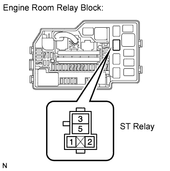
INSPECT ST RELAY
-
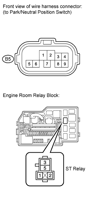
Remove the ST relay from the engine room relay block.
-
Measure the resistance according to the value(s) in the table below.
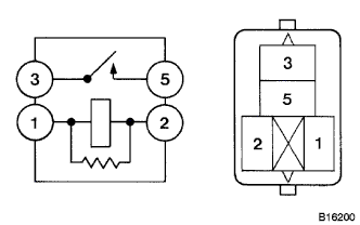
Standard resistance Tester Connection Condition Specified Condition 3 - 5 When no battery voltage applied terminals 1 and 2 10 kΩ or higher 3 - 5 When battery voltage applied terminals 1 and 2 Below 1 Ω -
Reinstall the ST relay.
NG 
REPLACE ST RELAY
OK
-
-
CHECK HARNESS AND CONNECTOR (PARK/NEUTRAL POSITION SWITCH - ST RELAY)
-
Disconnect the park/neutral position switch connector.
-
Remove the ST relay from the engine room relay block.
-
Measure the resistance according to the value(s) in the table below.
Standard resistance (check for open) Tester Connection Condition Specified Condition B5-5 - ST relay terminal (2) Always Below 1 Ω Standard resistance (check for short) Tester Connection Condition Specified Condition B5-5 or ST relay terminal (2) - Body ground Always 10 kΩ or higher -
Reconnect the park/neutral position switch connector.
-
Reinstall the ST relay.
NG
REPAIR OR REPLACE HARNESS OR CONNECTOR (PARK/NEUTRAL POSITION SWITCH - ST RELAY)
OK
-
-
CHECK HARNESS AND CONNECTOR (ST RELAY - BODY GROUND)
-
Remove the ST relay from the engine room relay block.
-
Measure the resistance according to the value(s) in the table below.
Standard resistance Tester Connection Condition Specified Condition ST relay terminal (2) - Body ground Always Below 1 Ω -
Reinstall the ST relay to the engine room relay block.
NG
REPAIR OR REPLACE HARNESS OR CONNECTOR (ST RELAY - BODY GROUND)
OK
-
-
INSPECT TERMINAL VOLTAGE (ST RELAY TERMINAL)
-
Remove the ST relay from the engine room relay block.
-
Measure the voltage according to the value(s) in the table below.
Standard voltage Tester Connection Condition Specified Condition ST relay terminal (5) - Body ground Always 9 to 14 V -
Reinstall the ST relay to the engine room relay block.
NG
INSPECT FUSIBLE LINK (ST FUSE) Click here
OK
-
-
INSPECT STARTER ASSEMBLY
-
Inspect the starter assembly Click here.
NG
REPLACE STARTER ASSEMBLY Click here
OK
-
-
CHECK HARNESS AND CONNECTOR (ST RELAY - STARTER ASSEMBLY)
-
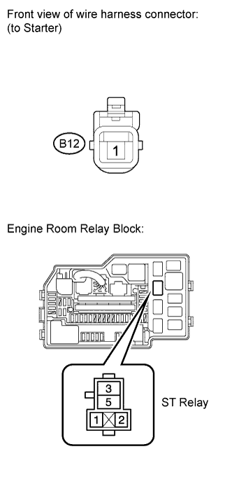
Remove the ST relay from the engine room relay block.
-
Disconnect the starter connector.
-
Measure the resistance according to the value(s) in the table below.
Standard resistance (check for open) Tester Connection Condition Specified Condition ST relay terminal (3) - B12-1 Always Below 1 Ω Standard resistance (check for short) Tester Connection Condition Specified Condition ST relay terminal (3) or B12-1 - Body ground Always 10 kΩ or higher -
Reconnect the starter connector.
-
Reinstall the ST relay.
NG
REPAIR OR REPLACE HARNESS OR CONNECTOR (ST RELAY - STARTER ASSEMBLY)
OK
REPAIR OR REPLACE HARNESS OR CONNECTOR (BATTERY - STARTER ASSEMBLY)
-
-
INSPECT FUSIBLE LINK (ST FUSE)
-
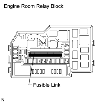
Remove the fusible link from the engine room relay block.
-
Measure the resistance according to the value(s) in the table below.
Standard resistance Tester Connection Condition Specified Condition Fusible link Always Below 1 Ω -
Reinstall the fusible link.
NG
REPLACE FUSIBLE LINK
OK
REPAIR OR REPLACE HARNESS OR CONNECTOR (BATTERY - STARTER RELAY)
-
-
CHECK ECM (STAR AND STSW VOLTAGE)
-
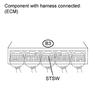
Start the engine.
-
Measure the voltage according to the value(s) in the table below.
Standard voltage Tester Connection Condition Specified Condition B3-12 (STSW) - Body ground Cranking 9 to 14 V Result Terminal STAR Terminal STSW Proceed to 9 to 14 V 9 to 14 V A 0 V 9 to 14 V B 0 V 0 V C
B
REPLACE ECM Click here
C
CHECK HARNESS AND CONNECTOR (ECM - MAIN BODY ECU) Click here
A
-
-
INSPECT PARK/NEUTRAL POSITION SWITCH
-
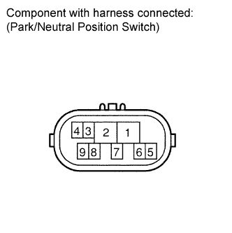
Disconnect the park/neutral position switch connector.
-
Measure the resistance according to the value(s) in the table below.
Standard resistance Shift Position Tester Connection Specified Condition P 2 - 6, 4 - 5 Below 1 Ω R 1 - 2 Below 1 Ω N 2 - 9, 4 - 5 Below 1 Ω D 2 - 7 Below 1 Ω 2 2 - 3 Below 1 Ω L 2 - 8 Below 1 Ω Result: Result Proceed To OK A NG (with U151E)) B NG (with U151F) C -
Reconnect the park/neutral position switch connector.
B
REPLACE PARK/NEUTRAL POSITION SWITCH Click here
C
REPLACE PARK/NEUTRAL POSITION SWITCH Click here
A
-
-
CHECK HARNESS AND CONNECTOR (ECM - PARK/NEUTRAL POSITION SWITCH)
-
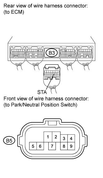
Disconnect the ECM connector.
-
Disconnect the park/neutral position switch connector.
-
Measure the resistance according to the value(s) in the table below.
Standard resistance (check for open) Tester Connection Condition Specified Condition B3-11 (STA) - B5-5 Always Below 1 Ω Standard resistance (check for short) Tester Connection Condition Specified Condition B3-11 (STA) or B5-5 - Body ground Always 10 kΩ or higher -
Reconnect the ECM connector.
-
Reconnect the park/neutral position switch connector.
NG
REPAIR OR REPLACE HARNESS OR CONNECTOR (ECM - PARK/NEUTRAL POSITION SWITCH)
OK
-
-
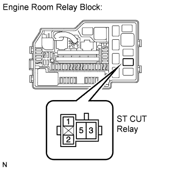
INSPECT RELAY (ST CUT RELAY)
-
Remove the ST CUT relay from the engine room relay block.
-
Measure the resistance according to the value(s) in the table below.
Standard resistance Tester Connection Condition Specified Condition 3 - 5 When no battery voltage applied terminals 1 and 2 10 kΩ or higher 3 - 5 When battery voltage applied terminals 1 and 2 Below 1 Ω -
Reinstall the ST CUT relay.
NG
REPLACE RELAY
OK
-
-
INSPECT TERMINAL VOLTAGE (ST CUT RELAY TERMINAL)
-
Remove the ST CUT relay from the engine room relay block.
-
Turn the ignition switch on (IG).
-
Measure the voltage according to the value(s) in the table below.
Standard voltage Tester Connection Switch Condition Specified Condition 2 - Body ground Ignition switch on (IG) 9 to 14 V -
Reinstall the ST CUT relay.
NG
REPAIR OR REPLACE HARNESS OR CONNECTOR (ST CUT RELAY - IG2 RELAY)
OK
REPAIR OR REPLACE HARNESS OR CONNECTOR (ST CUT RELAY - BODY GROUND)
-
-
CHECK HARNESS AND CONNECTOR (ECM - MAIN BODY ECU)
-
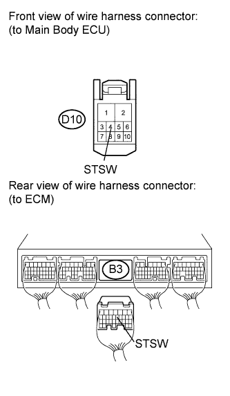
Disconnect the ECM connector.
-
Disconnect the main body ECU connector.
-
Measure the resistance according to the value(s) in the table below.
Standard resistance (check for open) Tester Connection Condition Specified Condition B3-12 (STSW) - D9-4 (STSW) Always Below 1 Ω Standard resistance (check for short) Tester Connection Condition Specified Condition B3-12 (STSW) or D9-4 (STSW) - Body ground Always 10 kΩ or higher -
Reconnect the ECM connector.
-
Reconnect the main body ECU connector.
NG
REPAIR OR REPLACE HARNESS OR CONNECTOR (ECM - IGNITION SWITCH ASSEMBLY)
OK
CHECK SMART ENTRY AND START SYSTEM Click here
-