| DTC Code | DTC Name |
|---|---|
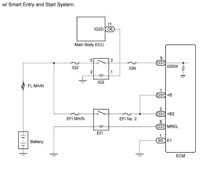
| ECM Power Source Circuit |
DESCRIPTION
When the ignition switch is turned on (IG), the battery voltage is applied to terminal IGSW of the ECM. The ECM MREL output signal causes a current to flow to the coil, closing the contacts of the EFI relay and supplying power to terminal +B and +B2 of the ECM.
If the ignition switch is turned off, the ECM holds the EFI relay ON for a maximum of 2 seconds to allow for the initial setting of the throttle valve.
INSPECTION PROCEDURE
PROCEDURE
- Click here
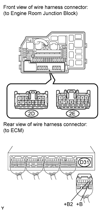
INSPECT ECM (+B AND +B2 VOLTAGE)
-
Turn the ignition switch on (IG).
-
Measure the voltage according to the value(s) in the table below.
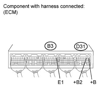
Standard voltage Tester Connection Switch Condition Specified Condition D31-1 (+B) - B3-1 (E1) Ignition switch on (IG) 9 to 14 V D31-2 (+B2) - B3-1 (E1) Ignition switch on (IG) 9 to 14 V
- OKClick here
- NGClick here
-
- Click here
CHECK HARNESS AND CONNECTOR (ECM - BODY GROUND)
-
Disconnect the ECM connector.
-
Measure the resistance according to the value(s) in the table below.
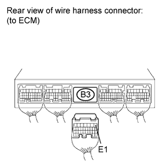
Standard resistance Check for open Tester Connection Condition Specified Condition B3-1 (E1) - Body ground Always Below 1 Ω -
Reconnect the ECM connector.
- OKClick here
- NGClick here
-
- Click here
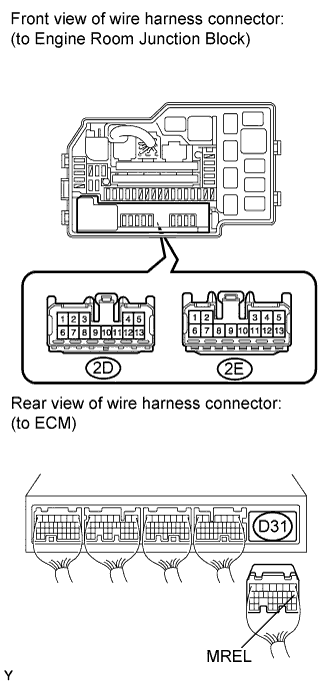
INSPECT ECM (MREL VOLTAGE)
-
Turn the ignition switch on (IG).
-
Measure the voltage according to the value(s) in the table below.
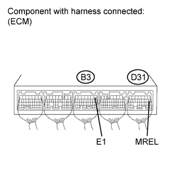
Standard voltage Tester Connection Switch Condition Specified Condition D31-8 (MREL) - B3-1 (E1) Ignition switch on (IG) 9 to 14 V
- OKClick here
- NGClick here
-
- Click here
CHECK FUSE (EFI MAIN AND EFI NO. 2 FUSE)
-
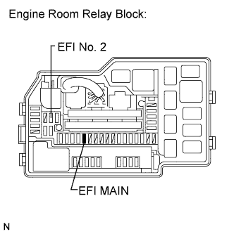
Remove the EFI MAIN and EFI No. 2 fuse from the engine room relay block.
-
Measure the resistance according to the value(s) in the table below.
Standard resistance Tester Connection Condition Specified Condition EFI MAIN fuse Always Below 1 Ω EFI No. 2 fuse Always Below 1 Ω -
Reinstall the fuses.
- OKClick here
- NGClick here
-
- Click here
INSPECT ENGINE ROOM JUNCTION BLOCK ASSEMBLY (EFI RELAY)
-
Inspect the EFI relay (Click here).
- OKClick here
- NGClick here
-
- Click here
CHECK HARNESS AND CONNECTOR (EFI MAIN RELAY - ECM, EFI RELAY - BODY GROUND)
-
Remove the engine room junction block from the engine room relay block.
-
Disconnect the ECM connector.
-
Measure the resistance according to the value(s) in the table below.
Standard resistance Check for open Tester Connection Condition Specified Condition 2E-9 (EFI relay terminal) - D31-8 (MREL) Always Below 1 Ω 2E-10 (EFI relay terminal) - Body ground Always Below 1 Ω Check for short Tester Connection Condition Specified Condition 2E-9 (EFI relay terminal) or D31-8 (MREL) - Body ground Always 10 kΩ or higher -
Reinstall the engine room junction block.
-
Reconnect the ECM connector.
- OKClick here
- NGClick here
-
- Click here
CHECK HARNESS AND CONNECTOR (EFI MAIN RELAY - ECM)
-
Remove the engine room junction block from the engine room relay block.
-
Disconnect the ECM connector.
-
Measure the resistance according to the value(s) in the table below.
Standard resistance Check for open Tester Connection Condition Specified Condition 2E-6 (EFI relay terminal) - D31-1 (+B) Always Below 1 Ω 2E-6 (EFI relay terminal) - D31-2 (+B2) Always Below 1 Ω Check for short Tester Connection Condition Specified Condition 2E-6 (EFI relay terminal) or D31-1 (+B) - Body ground Always 10 kΩ or higher 2E-6 (EFI relay terminal) or D31-2 (+B2) - Body ground Always 10 kΩ or higher -
Reinstall the engine room junction block.
-
Reconnect the ECM connector.
- OKClick here
- NGClick here
-
- Click here
INSPECT ECM (IGSW VOLTAGE)
-
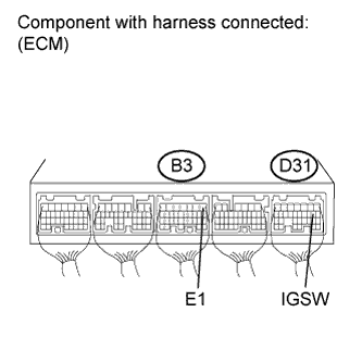
Turn the ignition switch on (IG).
-
Measure the voltage according to the value(s) in the table below.
Standard voltage Tester Connection Switch Condition Specified Condition D31-9 (IGSW) - B3-1 (E1) Ignition switch on (IG) 9 to 14 V
- OKClick here
- NGClick here
-
- Click here
CHECK HARNESS AND CONNECTOR (ECM - IG2 RELAY)
-
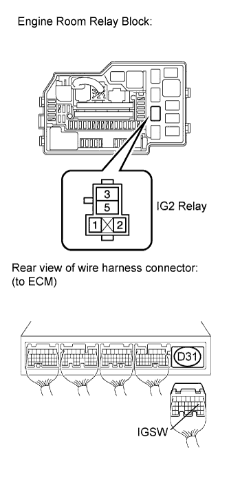
Remove the IG2 relay from the engine room relay block.
-
Disconnect the ECM connector.
-
Measure the resistance according to the value(s) in the table below.
Standard resistance Tester Connection Condition Specified Condition IG2 relay terminal 3 - D31-9 (IGSW) Always Below 1 Ω -
Reconnect the ECM connector.
-
Reinstall the IG2 relay.
- OKClick here
- NGClick here
-
- Click here
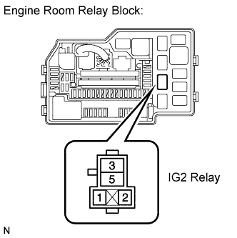
INSPECT IG2 RELAY
-
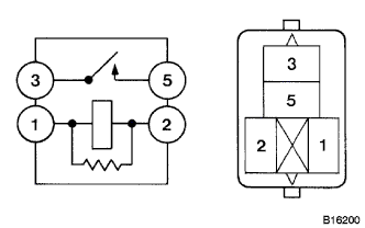
Remove the IG2 relay from the engine room relay block.
-
Measure the resistance according to the value(s) in the table below.
Standard resistance Tester Connection Condition Specified Condition 3 - 5 When no battery voltage applied to terminals 1 and 2 10 kΩ or higher When battery voltage applied to terminals 1 and 2 Below 1 Ω -
Reinstall the IG2 relay.
- OKClick here
- NGClick here
-
- Click here
CHECK HARNESS AND CONNECTOR (IG2 RELAY POWER SOURCE)
-
Remove the IG2 relay from the engine room relay block.
-
Turn the ignition switch on (IG)
-
Measure the voltage according to the value(s) in the table below.
Standard voltage Tester Connection Switch Condition Specified Condition 5 - Body ground Ignition switch on (IG) 9 to 14 V -
Reinstall the IG2 relay.
- OKClick here
- NGClick here
-
- Click here
CHECK HARNESS AND CONNECTOR (IG2 RELAY - BODY GROUND)
-
Remove the IG2 relay from the engine room relay block.
-
Measure the resistance according to the value(s) in the table below.
Standard resistance Tester Connection Condition Specified Condition 2 - Body ground Always Below 1 Ω -
Reinstall the IG2 relay.
Result Result Proceed to NG A OK (w/o Smart entry and star system) B OK (w/ Smart entry and star system) C
-
- Click here
CHECK FUSE (IG2 FUSE)
-
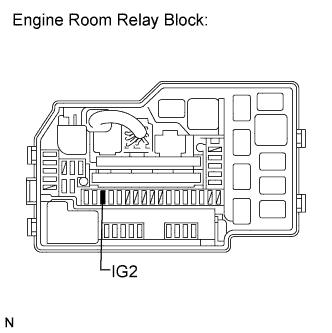
Remove the IG2 fuse from the engine room relay block.
-
Measure the resistance according to the value(s) in the table below.
Standard resistance Tester Connection Condition Specified Condition IG2 fuse Always Below 1 Ω -
Reinstall the IG2 fuse
- OKClick here
- NGClick here
-
- Click here
CHECK FUSE (IGN FUSE)
-
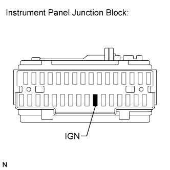
Remove the IGN fuse from the instrument panel junction block.
-
Measure the resistance according to the value(s) in the table below.
Standard resistance Tester Connection Condition Specified Condition IGN fuse Always Below 1 Ω -
Reinstall the IGN fuse.
- OKClick here
- NGClick here
-
- Click here
CHECK HARNESS AND CONNECTOR (IGNITION SWITCH - IG2 RELAY)
-
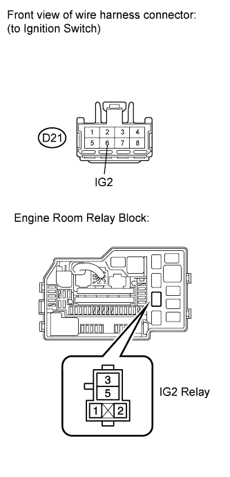
Remove the IG2 relay from the engine room relay block.
-
Disconnect the ignition switch connector.
-
Measure the resistance according to the value(s) in the table below.
Standard resistance Check for open Tester Connection Condition Specified Condition D21-6 (IG2) - IG2 relay terminal 1 Always Below 1 Ω Check for short Tester Connection Condition Specified Condition D21-6 (IG2) or IG2 relay terminal 1 - Body ground Always 10 kΩ or higher -
Reinstall the IG2 relay.
-
Reconnect the ignition switch connector.
- OKClick here
- NGClick here
-
- Click here
INSPECT IGNITION SWITCH
-
Inspect the ignition or starter switch assembly (Click here).
- OKClick here
- NGClick here
-
- Click here
CHECK HARNESS AND CONNECTOR (IG2 RELAY - MAIN BODY ECU, IG2 RELAY - BODY GROUND)
-
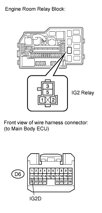
Remove the IG2 relay from the engine room relay block.
-
Remove the instrument panel junction block (main body ECU).
-
Measure the resistance according to the value(s) in the table below.
Standard resistance (Check for open) Tester Connection Condition Specified Condition IG2 relay terminal (1) - D6-11 (IG2D) Always Below 1 Ω IG2 relay terminal (2) - Body ground Always Below 1 Ω Standard resistance (Check for short) Tester Connection Condition Specified Condition D6-11 (IG2D) - Body ground Always 10 kΩ or higher -
Reinstall the IG2 relay.
-
Reconnect the main body ECU connector.
- OKClick here
- NGClick here
-
- Click here
PROCEED TO NEXT CIRCUIT INSPECTION SHOWN IN PROBLEM SYMPTOMS TABLE
- Click here
REPAIR OR REPLACE HARNESS OR CONNECTOR (ECM - BODY GROUND)
- Click here
REPLACE FUSE (EFI MAIN OR EFI NO. 2 FUSE)
- Click here
REPLACE RELAY (EFI RELAY)Click here
- Click here
REPAIR OR REPLACE HARNESS OR CONNECTOR (EFI MAIN RELAY - ECM)
- Click here
REPLACE ECMClick here
- Click here
REPLACE IG2 RELAY
- Click here
REPAIR OR REPLACE HARNESS OR CONNECTOR (IG2 RELAY - BODY GROUND)
- Click here
REPLACE FUSE (IG2 FUSE)
- Click here
REPAIR OR REPLACE HARNESS OR CONNECTOR (IG2 RELAY - BATTERY)
- Click here
REPLACE FUSE (IGN FUSE)
- Click here
REPAIR OR REPLACE HARNESS OR CONNECTOR (IG2 RELAY - ECM)
- Click here
REPAIR OR REPLACE HARNESS OR CONNECTOR (IGNITION SWITCH - IG2 RELAY)
- Click here
REPLACE IGNITION SWITCHClick here
- Click here
REPAIR OR REPLACE HARNESS OR CONNECTOR (IGNITION SWITCH - BATTERY)
- Click here
CHECK SMART ENTRY AND START SYSTEMClick here
- Click here
REPAIR OR REPLACE HARNESS OR CONNECTOR
- Click here
REPAIR OR REPLACE HARNESS OR CONNECTOR (EFI MAIN RELAY - EFI MAIN FUSE)