SFI SYSTEM Active Control Engine Mount System
DESCRIPTION
The active control engine mount system decreases engine vibration at an engine idling using the active control engine mount VSV. The VSV is controlled by a pulse signal transmitted to the VSV from the ECM. The frequency of this pulse signal is matched to the engine speed to decrease engine vibration.
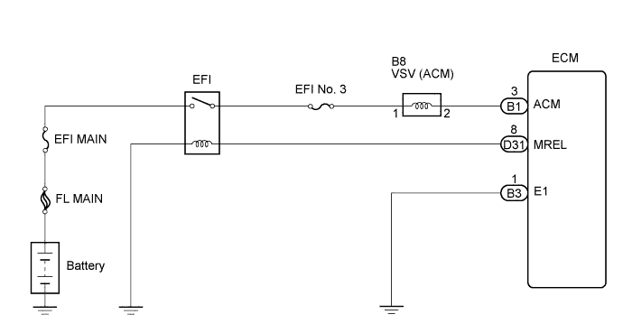
WIRING DIAGRAM
INSPECTION PROCEDURE
PROCEDURE
-
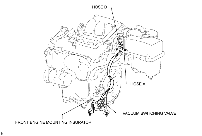
CHECK VACUUM HOSES
-
Check the air and vacuum hoses for looseness, disconnection and blockage. If the hose is damaged, replace the vacuum hose assembly.
NG 
REPAIR OR REPLACE VACUUM HOSES
OK 
-
-
CHECK VACUUM
-
Start the engine.
-
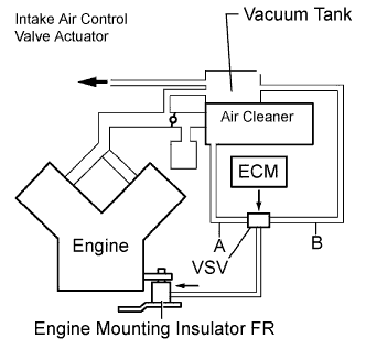
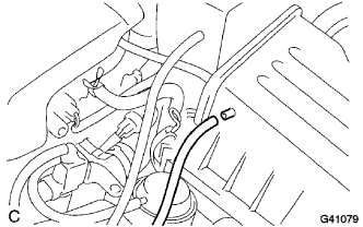
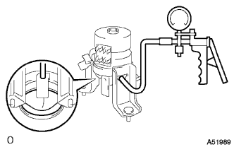
Disconnect the vacuum hose from the air cleaner cap.
-
Check that the disconnected port located on the vacuum tank applies suction to your finger.
OK Vacuum pressure exists. -
Reconnect the vacuum hose.
NG
CHECK AND REPLACE VACUUM SOURCE AND HOSES
OK
-
-
INSPECT ECM
-
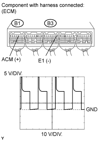
Connect the oscilloscope between terminals ACM and E1 of the ECM connectors.
-
Warm up the engine to normal operating temperature.
-
Turn the A/C switch on.
-
Measure the voltage according to the value(s) in the table below.
Standard voltage Tester Connection Condition Voltage B1-3 (ACM) - B3-1 (E1) Shift position is D, and engine speed is 850 rpm or less Pulse generation Shift position is D, and engine speed is 950 rpm or more 9 to 14 V Shift position is P 9 to 14 V
NG 
INSPECT DUTY VACUUM SWITCHING VALVE (RESISTANCE) Click here
OK
-
-
INSPECT DUTY VACUUM SWITCHING VALVE (OPERATION)
-
Remove the VSV for ACM.
-
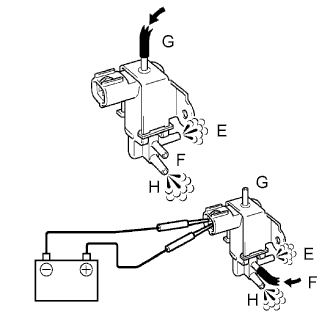
Check operation of the VSV for ACM when positive battery voltage is applied to the terminals of the VSV for ACM connector.
Positive battery voltage is not applied The air from pipe G is flowing out through pipes E and H. Positive battery voltage is applied The air from pipe F is flowing out through pipes E and H. -
Reinstall the VSV for ACM.
NG
REPLACE DUTY VACUUM SWITCHING VALVE
OK
-
-
INSPECT ENGINE MOUNTING INSULATOR ASSEMBLY FRONT
-
Disconnect the vacuum hose from the front engine mount insulator.
-
Using vacuum pump, apply vacuum of 80 kPa (600 mmHg, 25 in.Hg) and wait for 1 minute.
-
Check that there is no change in the needle movement of the vacuum pump gauge.
-
Check that there is no fluid leakage caused by a break in the diaphragm.
OK Vacuum pressure exists. -
Reconnect the vacuum hose.
NG
REPLACE ENGINE MOUNTING INSULATOR ASSEMBLY FRONT
OK 
SYSTEM OK
-
-
INSPECT DUTY VACUUM SWITCHING VALVE (RESISTANCE)
-
Disconnect the VSV for ACM connector.
-
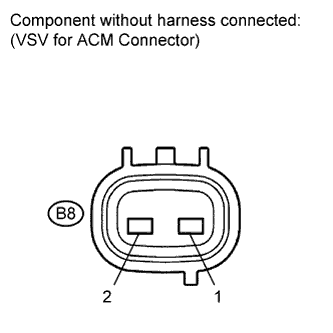
Measure the resistance according to the value(s) in the table below.
Standard resistance Tester Connection Condition Specified Condition 1 - 2 20°C (68°F) 19 to 21 Ω -
Reconnect the VSV for ACM connector.
NG
REPLACE DUTY VACUUM SWITCHING VALVE Click here
OK
-
-
CHECK HARNESS AND CONNECTOR (VSV FOR ACM - ECM, VSV FOR ACM - EFI RELAY)
-
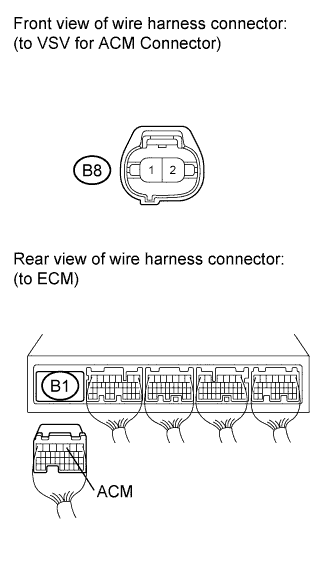
Disconnect the VSV for ACM connector.
-
Disconnect the ECM connector.
-
Measure the resistance according to the value(s) in the table below.
Standard resistance (Check for open) Tester Connection Condition Specified Condition B8-2 - B1-3 (ACM) Always Below 1 Ω Standard resistance (Check for open) Tester Connection Condition Specified Condition B8-2 or B1-3 (ACM) - Body ground Always 10 kΩ or higher -
Reconnect the ECM connector.
-
Reconnect the VSV connector.
NG
REPAIR OR REPLACE HARNESS OR CONNECTOR (VSV FOR ACM - ECM)
OK
REPAIR OR REPLACE HARNESS OR CONNECTOR (VSV FOR ACM - EFI NO. 3 FUSE)
-