| DTC Code | DTC Name |
|---|---|
| P1660 | VSV for AICVS Circuit |
DESCRIPTION
The air cleaner is equipped with two inlets, one of which is opened or closed by the air intake control valve. This system reduces intake noise and increases engine power at low to high engine speeds range.
When the engine is operating in the low-to-mid speed range, this control operates the air intake control valve to close one of the air cleaner inlets. When the engine speed is more than 3600 rpm and the opening angle of the throttle valve is more than 60°, the ECM activates the VSV and opens the air intake control valve.
| DTC No. | Detection Condition | Trouble Area |
|---|---|---|
| P1660 | The following conditions are met simultaneously for 0.5 seconds or more (2 trip detection logic):
|
|
INSPECTION PROCEDURE
PROCEDURE
- Click here
PERFORM ACTIVE TEST USING INTELLIGENT TESTER (CONTROL THE VSV FOR AICS)
-
Turn the ignition switch on (IG) and turn the intelligent tester on.
-
Select the following menu items: Powertrain / Engine and ECT / Active Test /Control the VSV for AICS.
-
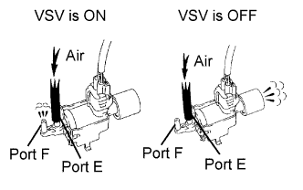
Check the operation of the VSV when the VSV is operated by the intelligent tester.
OK Tester Operation Specified Condition VSV is ON Air from port E flows out through port F VSV is OFF Air from port E flows out through the air filter
- OKClick here
- NGClick here
-
- Click here
INSPECT VACUUM TANK
-
Inspect the vacuum tank (Click here).
- OKClick here
- NGClick here
-
- Click here
CHECK VSV ASSEMBLY (FOR AIR INTAKE CONTROL VALVE)
-
Inspect the VSV for AICV (Click here).
- OKClick here
- NGClick here
-
- Click here
INSPECT TERMINAL VOLTAGE (VSV FOR AIR INTAKE CONTROL VALVE CONNECTOR)
-
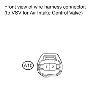
Disconnect the VSV for air intake control valve connector.
-
Turn the ignition switch on (IG).
-
Measure the voltage according to the value(s) in the table below.
Standard voltage Tester Connection Switch Condition Specified Condition 1 - Body ground Ignition switch on (IG) 9 to 14 V
- OKClick here
- NGClick here
-
- Click here
CHECK HARNESS AND CONNECTOR (VSV FOR AIR INTAKE CONTROL VALVE - ECM)
-
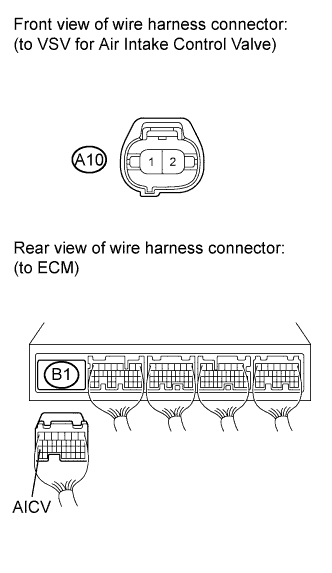
Disconnect the VSV for air intake control valve connector.
-
Disconnect the ECM connector.
-
Measure the resistance according to the value(s) in the table below.
Standard resistance (Check for open) Tester Connection Condition Specified Condition A10-2 - B1-27 (AICV) Always Below 1 Ω Standard resistance (Check for short) Tester Connection Condition Specified Condition A10-2 or B1-27 (AICV) - Body ground Always 10 kΩ or higher -
Reconnect the ECM connector.
-
Reconnect the VSV for air intake control valve connector.
- OKClick here
- NGClick here
-
- Click here
REPAIR OR REPLACE AIR CLEANER CAP
- Click here
REPLACE ECMClick here
- Click here
REPLACE VACUUM SWITCHING VALVEClick here
- Click here
REPAIR OR REPLACE HARNESS OR CONNECTOR (EFI NO. 3 FUSE - VSV FOR AIR INTAKE CONTROL VALVE)
- Click here
REPAIR OR REPLACE HARNESS OR CONNECTOR