SFI SYSTEM, Diagnostic DTC:P0560
| DTC Code | DTC Name |
|---|---|
| P0560 | System Voltage |
DESCRIPTION
The battery supplies electricity to the ECM even when the ignition switch is off. This power allows the ECM to store data such as DTC history, freeze frame data and fuel trim values. If the battery voltage falls below a minimum level, these memories are cleared and the ECM determines that there is a malfunction in the power supply circuit. When the engine is next started, the ECM will illuminate the MIL and set the DTC.
| DTC No. | DTC Detection Condition | Trouble Area |
|---|---|---|
| P0560 | Open in ECM back-up power source circuit (1 trip detection logic) |
|
Tech Tips
If DTC P0560 is set, the ECM does not store other DTCs.
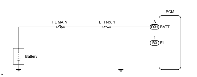
WIRING DIAGRAM
INSPECTION PROCEDURE
Tech Tips
Read freeze frame data using the intelligent tester. The ECM records vehicle and driving condition information as freeze frame data the moment a DTC is stored. When troubleshooting, freeze frame data can be helpful in determining whether the vehicle was running or stopped, whether the engine was warmed up or not, whether the air fuel ratio was lean or rich, as well as other data recorded at the time of a malfunction.
PROCEDURE
-
CHECK FUSE (EFI NO. 1 FUSE)
-
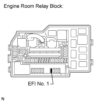
Remove the EFI No.1 fuse from the engine room relay block.
-
Measure the resistance according to the value(s) in the table below.
Standard resistance Tester Connection Condition Specified Condition EFI No. 1 Fuse Always Below 1 Ω -
Reinstall the EFI No. 1 fuse.
NG 
CHECK FOR SHORT IN ALL HARNESS AND COMPONENTS CONNECTED TO FUSE, AND REPLACE FUSE (EFI NO. 1 FUSE)
OK 
-
-
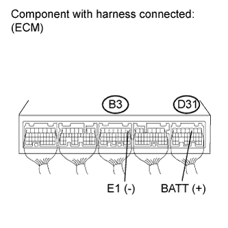
INSPECT ECM (BATT VOLTAGE)
-
Measure the voltage according to the value(s) in the table below.
Standard voltage Tester Connection Condition Specified Condition D31-3 (BATT) - B3-1 (E1) Always 9 to 14 V
NG 
CHECK HARNESS AND CONNECTOR (ECM - EFI NO. 1 FUSE) Click here
OK 
CHECK FOR INTERMITTENT PROBLEMS Click here
-
-
CHECK HARNESS AND CONNECTOR (ECM - EFI NO. 1 FUSE)
-
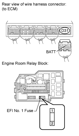
Remove the EFI No. 1 fuse from the relay block.
-
Disconnect the ECM connector.
-
Measure the resistance according to the value(s) in the table below.
Standard resistance (Check for open) Tester Connection Condition Specified Condition EFI No. 1 fuse (2) - D31-3 (BATT) Always Below 1 Ω Standard resistance (Check for short) Tester Connection Condition Specified Condition EFI No. 1 fuse (2) or D31-3 (BATT) - Body ground Always 10 kΩ or higher -
Reconnect the ECM connector.
-
Reinstall the EFI No. 1 fuse.
NG
REPAIR OR REPLACE HARNESS OR CONNECTOR
OK
CHECK AND REPLACE ENGINE ROOM RELAY BLOCK
-