SFI SYSTEM, Diagnostic DTC:P0500
| DTC Code | DTC Name |
|---|---|
| P0500 | Vehicle Speed Sensor "A" |
DESCRIPTION
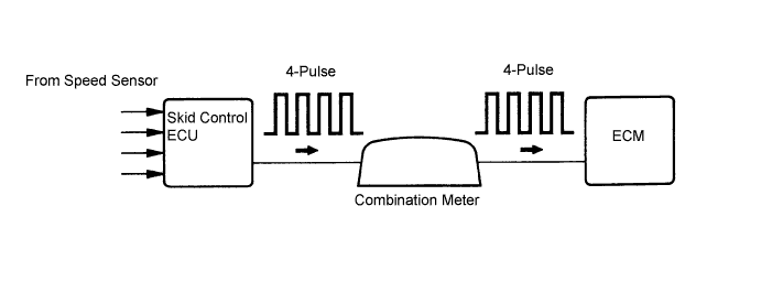
The speed sensor detects the wheel speed and sends the appropriate signals to the skid control ECU.
The skid control ECU converts these wheel speed signals into a 4-pulse signal and outputs it to the ECM via the combination meter. The ECM determines the vehicle speed based on the frequency of these pulse signals.
| DTC No. | DTC Detection Condition | Trouble Area |
|---|---|---|
| P0500 | Both of the following conditions (A) and (B) are met (1 trip detection logic) (A) Either of the following conditions 1 or 2 is met
(B) While vehicle is being driven, no vehicle speed sensor signal is sent to ECM |
|
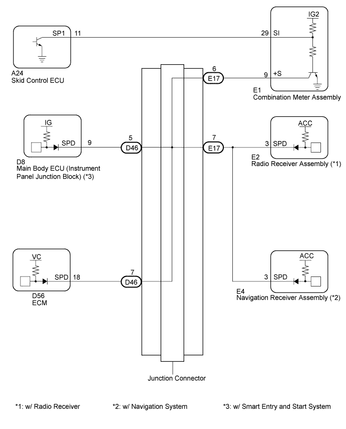
WIRING DIAGRAM
INSPECTION PROCEDURE
Tech Tips
Read freeze frame data using the intelligent tester. The ECM records vehicle and driving condition information as freeze frame data the moment a DTC is stored. When troubleshooting, freeze frame data can be helpful in determining whether the vehicle was running or stopped, whether the engine was warmed up or not, whether the air fuel ratio was lean or rich, as well as other data recorded at the time of a malfunction.
PROCEDURE
-
READ VALUE USING INTELLIGENT TESTER (VEHICLE SPEED)
-
Drive the vehicle and check whether the operation of the speedometer in the combination meter is normal.
Tech Tips
-
The vehicle speed sensor is operating normally if the speedometer reading is normal.
-
If the speedometer does not operate, check it by following the procedure described in speedometer circuit.
-
-
Connect the intelligent tester to the DLC3.
-
Turn the ignition switch on (IG).
-
Turn the tester on.
-
Enter the following menus: Powertrain / Engine and ECT / Data List / Vehicle Speed.
-
Drive the vehicle.
-
Read the value displayed on the tester.
OK Vehicle speeds displayed on tester and speedometer display are equal.
NG 
INSPECT COMBINATION METER ASSEMBLY (OUTPUT WAVEFORM) Click here
OK 
CHECK FOR INTERMITTENT PROBLEMS Click here
-
-
INSPECT COMBINATION METER ASSEMBLY (OUTPUT WAVEFORM)
-
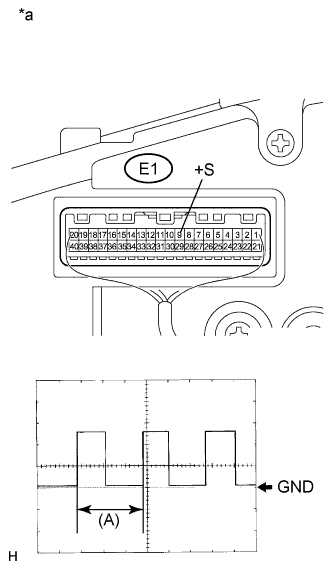
Text in Illustration *a Component with harness connected
(Combination Meter Assembly)
Remove the combination meter.
-
Connect the oscilloscope to terminal E1-9 (+S) and body ground.
-
Turn the ignition switch on (IG).
-
Turn the wheel slowly.
-
Check the signal waveform according to the condition(s) in the table below.
Item Condition Tool setting 5 V / DIV., 20 ms / DIV. Vehicle condition Driving at approx. 20 km/h (12 mph) OK The waveform is displayed as shown in the illustration. Tech Tips
When the system is functioning normally, one wheel revolution generates 4 pulses. As the vehicle speed increases, the width indicated by (A) in the illustration narrows.
NG 
GO TO SPEED SIGNAL CIRCUIT Click here
OK 
-
-
CHECK HARNESS AND CONNECTOR (COMBINATION METER ASSEMBLY - ECM)
-
Disconnect the combination meter connector.
-
Disconnect the ECM connector.
-
Measure the resistance according to the value(s) in the table below.
Standard resistance (Check for open) Tester Connection Condition Specified Condition E1-9 (+S) - D56-18 (SPD) Always Below 1 Ω -
Reconnect the combination meter connector.
-
Reconnect the ECM connector.
NG
REPAIR OR REPLACE HARNESS OR CONNECTOR
OK
REPLACE ECM Click here
-