SFI SYSTEM Starter Signal Circuit
DESCRIPTION
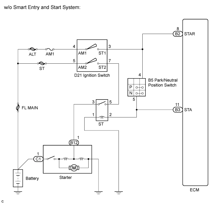
While the engine is being cranked, current flows from terminal ST1 of the ignition switch to the park/neutral position switch (for automatic transaxle) and also flows to terminal STA of the ECM (STA Signal).
WIRING DIAGRAM
INSPECTION PROCEDURE
Tech Tips
This chart is based on the premise that the engine can crank normally. If the engine cannot crank normally, proceed to the problem symptoms table Click here.
PROCEDURE
-
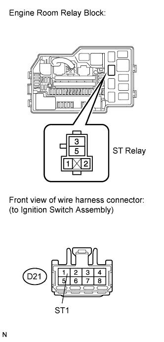
INSPECT TERMINAL VOLTAGE (ST RELAY TERMINAL)
-
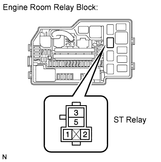
Remove the ST relay from the engine room relay block.
-
Measure the voltage according to the value(s) in the table below.
Standard voltage Tester Connection Condition Specified Condition ST relay terminal 1 - Body ground Engine cranking 9 to 14 V Tech Tips
The engine does not crank because the relay is not installed.
-
Reinstall the ST relay.
NG 
INSPECT IGNITION SWITCH ASSEMBLY Click here
OK 
-
-
INSPECT ST RELAY
-
Remove the ST relay from the engine room relay block.
-
Measure the resistance according to the value(s) in the table below.
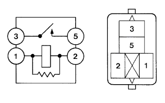
Standard resistance Tester Connection Condition Specified Condition 3 - 5 When no battery voltage applied terminals 1 and 2 10 kΩ or higher 3 - 5 When battery voltage applied terminals 1 and 2 Below 1 Ω -
Reinstall the ST relay.
NG 
REPLACE ST RELAY
OK
-
-
CHECK HARNESS AND CONNECTOR (ST RELAY - BODY GROUND)
-
Remove the ST relay from the engine room relay block.
-
Measure the resistance according to the value(s) in the table below.
Standard resistance Tester Connection Condition Specified Condition ST relay terminal 2 - Body ground Always Below 1 Ω -
Reinstall the ST relay.
NG
REPAIR OR REPLACE HARNESS OR CONNECTOR (ST RELAY - BODY GROUND)
OK
-
-
INSPECT TERMINAL VOLTAGE (ST RELAY TERMINAL)
-
Remove the ST relay from the engine room relay block.
-
Measure the voltage according to the value(s) in the table below.
Standard voltage Tester Connection Condition Specified Condition ST relay terminal 5 - Body ground Cranking 9 to 14 V -
Reinstall the ST relay.
NG
CHECK HARNESS AND CONNECTOR (ST RELAY - IGNITION SWITCH ASSEMBLY) Click here
OK
-
-
CHECK HARNESS AND CONNECTOR (ST RELAY - STARTER)
-
Remove the ST relay from the engine room relay block.
-
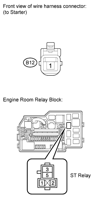
Disconnect the starter connector.
-
Measure the resistance according to the value(s) in the table below.
Standard resistance Tester Connection Condition Specified Condition ST relay terminal 3 - B12-1 Always Below 1 Ω -
Reconnect the starter connector.
-
Reinstall the ST relay.
NG
REPAIR OR REPLACE HARNESS OR CONNECTOR (ST RELAY - STARTER)
OK 
REPAIR OR REPLACE STARTER ASSEMBLY
-
-
CHECK HARNESS AND CONNECTOR (ST RELAY - IGNITION SWITCH ASSEMBLY)
-
Remove the ST relay from engine room relay block.
-
Disconnect the ignition switch assembly connector.
-
Measure the resistance according to the value(s) in the table below.
Standard resistance (Check for open) Tester Connection Condition Specified Condition ST relay terminal 5 - D21-2 (ST2) Always Below 1 Ω Standard resistance (Check for short) Tester Connection Condition Specified Condition ST relay terminal 5 or D21-2 (ST2) - Body ground Always 10 kΩ or higher -
Reinstall the ST relay.
-
Reconnect the ignition switch assembly connector.
NG
REPAIR OR REPLACE HARNESS OR CONNECTOR (ST RELAY - IGNITION SWITCH ASSEMBLY)
OK
-
-
INSPECT IGNITION SWITCH ASSEMBLY
-
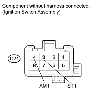
Disconnect the ignition switch assembly connector.
-
Measure the resistance according to the value(s) in the table below.
Standard resistance Tester Connection Ignition Switch Position Specified Condition All terminals LOCK 10 kΩ or higher D21-4 (AM1) - D21-3 (ST1) START Below 1 Ω -
Reconnect the ignition switch assembly connector.
NG
REPLACE IGNITION SWITCH ASSEMBLY Click here
OK
-
-
CHECK HARNESS AND CONNECTOR (ST RELAY - PARK/NEUTRAL POSITION SWITCH)
-
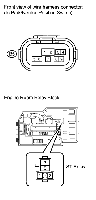
Remove the ST relay from the engine relay block.
-
Disconnect the park/neutral position switch connector.
-
Measure the resistance according to the value(s) in the table below.
Standard resistance (Check for open) Tester Connection Condition Specified Condition ST relay terminal 2 - B5-5 Always Below 1 Ω Standard resistance (Check for short) Tester Connection Condition Specified Condition ST relay terminal 2 or B5-5 - Body ground Always 10 kΩ or higher -
Reinstall the ST relay.
-
Reconnect the park/neutral position switch connector.
NG
REPAIR OR REPLACE HARNESS OR CONNECTOR (ST RELAY - PARK/NEUTRAL POSITION SWITCH)
OK
-
-
INSPECT PARK/NEUTRAL POSITION SWITCH
-
Inspect the park/neutral position switch (U151E: Click here, U151F: Click here.
Result: Result Proceed To OK A NG (with U151E) B NG (with U151F) C
B
REPLACE PARK/NEUTRAL POSITION SWITCH Click here
C
REPLACE PARK/NEUTRAL POSITION SWITCH Click here
A
-
-
CHECK HARNESS AND CONNECTOR (PARK/NEUTRAL POSITION SWITCH - IGNITION SWITCH ASSEMBLY)
-
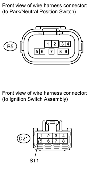
Disconnect the park/neutral position switch connector.
-
Disconnect the ignition switch assembly connector.
-
Measure the resistance according to the value(s) in the table below.
Standard resistance (Check for open) Tester Connection Condition Specified Condition B5-4 - D21-3 (ST1) Always Below 1 Ω Standard resistance (Check for short) Tester Connection Condition Specified Condition B5-4 or D21-3 (ST1) - Body ground Always 10 kΩ or higher -
Reconnect the park/neutral position switch connector.
-
Reconnect the ignition switch assembly connector.
NG
REPAIR OR REPLACE HARNESS OR CONNECTOR (PARK/NEUTRAL POSITION SWITCH - IGNITION SWITCH ASSEMBLY)
OK
-
-
INSPECT IGNITION SWITCH ASSEMBLY
-
Disconnect the ignition switch assembly connector.
-
Measure the resistance according to the value(s) in the table below.
Standard resistance Tester Connection Ignition Switch Position Specified Condition All terminals LOCK 10 kΩ or higher D21-4 (AM1) - D21-3 (ST1) START Below 1 Ω -
Reconnect the ignition switch assembly connector.
NG
REPLACE IGNITION SWITCH ASSEMBLY Click here
OK
-
-
INSPECT FUSE (AM1 FUSE)
-
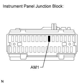
Remove the AM1 fuse from the instrument panel junction block.
-
Measure the resistance according to the value(s) in the table below.
Standard resistance Tester Connection Condition Specified Condition AM1 fuse Always Below 1 Ω -
Reinstall the AM1 fuse.
NG
REPLACE FUSE (AM1 FUSE)
OK
REPAIR OR REPLACE HARNESS OR CONNECTOR (IGNITION SWITCH ASSEMBLY - BATTERY)
-