| DTC Code | DTC Name |
|---|---|
| Fuel Pump Control Circuit |
INSPECTION PROCEDURE
Inspect the fuses for circuits related to this system before performing the following inspection procedure.
PROCEDURE
- Click here
CHECK FUEL PUMP OPERATION
-
Check the fuel pump operation (Click here).
- OKClick here
- NGClick here
-
- Click here
INSPECT TERMINAL VOLTAGE (FUEL PMP RELAY TERMINAL)
-
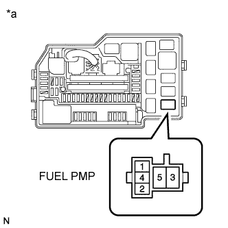
Remove the FUEL PMP relay from the engine room relay block.
-
Turn the ignition switch on (IG).
-
Measure the voltage according to the value(s) in the table below.
Standard Voltage Tester Connection Condition Specified Condition FUEL PMP relay terminal 2 - Body ground Ignition switch on (IG) 11 to 14 V FUEL PMP relay terminal 3 - Body ground Ignition switch on (IG) 11 to 14 V Table 1. Text in Illustration *a Engine Room Relay Block -
Reinstall the FUEL PMP relay.
- OKClick here
- NGClick here
-
- Click here
INSPECT FUEL PUMP RELAY
-
Remove the FUEL PMP relay from the engine room relay block.
-
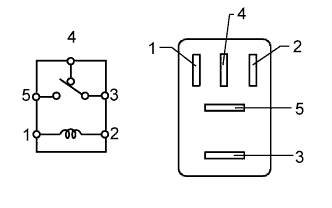
Measure the resistance according to the value(s) in the table below.
Standard Resistance Tester Connection Condition Specified Condition 3 - 4 No battery voltage applied across terminals 1 and 2 Below 1 Ω 3 - 4 Battery voltage applied across terminals 1 and 2 10 kΩ or higher 3 - 5 No battery voltage applied across terminals 1 and 2 10 kΩ or higher 3 - 5 Battery voltage applied across terminals 1 and 2 Below 1 Ω -
Reinstall the FUEL PMP relay.
- OKClick here
- NGClick here
-
- Click here
INSPECT FUEL PUMP RESISTOR
-
Inspect the fuel pump resistor (Click here).
- OKClick here
- NGClick here
-
- Click here
CHECK HARNESS AND CONNECTOR (FUEL PMP RELAY - FUEL PUMP RESISTOR)
-
Remove the FUEL PMP relay from the engine room relay block.
-
Disconnect the fuel pump resistor connector.
-
Measure the resistance according to the value(s) in the table below.
Standard Resistance (Check for Open) Tester Connection Condition Specified Condition FUEL PMP relay terminal 5 - A35-1 Always Below 1 Ω FUEL PMP relay terminal 4 - A35-2 Always Below 1 Ω Standard Resistance (Check for Short) Tester Connection Condition Specified Condition FUEL PMP relay terminal 5 or A35-1 - Body ground Always 10 kΩ or higher FUEL PMP relay terminal 4 or A35-2 - Body ground Always 10 kΩ or higher -
Reinstall the FUEL PMP relay.
-
Reconnect the fuel pump resistor connector.
- OKClick here
- NGClick here
-
- Click here
CHECK HARNESS AND CONNECTOR (FUEL PUMP - FUEL PMP RELAY)
-
Remove the FUEL PMP relay from the engine room relay block.
-
Disconnect the fuel pump connector.
-
Measure the resistance according to the value(s) in the table below.
Standard Resistance (Check for Open) Tester Connection Condition Specified Condition FUEL PMP relay terminal 4 - O9-4 Always Below 1 Ω Standard Resistance (Check for Short) Tester Connection Condition Specified Condition FUEL PMP relay terminal 4 or O9-4 - Body ground Always 10 kΩ or higher -
Reconnect the fuel pump connector.
-
Reinstall the FUEL PMP relay.
- OKClick here
- NGClick here
-
- Click here
CHECK HARNESS AND CONNECTOR (FUEL PMP RELAY - ECM)
-
Remove the FUEL PMP relay from the engine room relay block.
-
Disconnect ECM connector.
-
Measure the resistance according to the value(s) in the table below.
Standard Resistance (Check for Open) Tester Connection Condition Specified Condition FUEL PMP relay terminal 1 - D55-8 (FPR) Always Below 1 Ω Standard Resistance (Check for Short) Tester Connection Condition Specified Condition FUEL PMP relay terminal 1 or D55-8 (FPR) - Body ground Always 10 kΩ or higher -
Reconnect the ECM connector.
-
Reinstall the FUEL PMP relay.
- OKClick here
- NGClick here
-
- Click here
INSPECT FUEL PUMP
-
Inspect the fuel pump (Click here).
- OKClick here
- NGClick here
-
- Click here
CHECK HARNESS AND CONNECTOR (FUEL PUMP - FUEL PMP RELAY)
-
Disconnect the fuel pump connector.
-
Remove the FUEL PMP relay from the engine room relay block.
-
Measure the resistance according to the value(s) in the table below.
Standard Resistance (Check for Open) Tester Connection Condition Specified Condition O9-4 - FUEL PMP relay terminal 4 Always Below 1 Ω Standard Resistance (Check for Short) Tester Connection Condition Specified Condition O9-4 or FUEL PMP relay terminal 4 - Body ground Always 10 kΩ or higher -
Reinstall the FUEL PMP relay.
-
Reconnect the fuel pump connector.
- OKClick here
- NGClick here
-
- Click here
INSPECT ENGINE ROOM RELAY BLOCK (C/OPN RELAY - FUEL PMP RELAY)
-
Remove the engine room junction block assembly from the engine room relay block.
-
Disconnect the engine room junction block assembly connector.
-
Remove the FUEL PMP relay from the engine room relay block.
-
Measure the resistance according to the value(s) in the table below.
Standard Resistance (Check for Open) Tester Connection Condition Specified Condition 2E-13 - FUEL PMP relay terminal 2 Always Below 1 Ω 2E-13 - FUEL PMP relay terminal 3 Always Below 1 Ω Standard Resistance (Check for Short) Tester Connection Condition Specified Condition 2E-13 or FUEL PMP relay terminal 2 - Body ground Always 10 kΩ or higher 2E-13 or FUEL PMP relay terminal 3- Body ground Always 10 kΩ or higher -
Reconnect the engine room junction block assembly connector.
-
Reinstall the engine room junction block assembly.
-
Reinstall the FUEL PMP relay.
- OKClick here
- NGClick here
-
- Click here
CHECK HARNESS AND CONNECTOR (FUEL PUMP - BODY GROUND)
-
Disconnect the fuel pump connector.
-
Measure the resistance according to the value(s) in the table below.
Standard Resistance (Check for Open) Tester Connection Condition Specified Condition O9-5 - Body ground Always Below 1 Ω -
Reconnect the fuel pump connector.
- OKClick here
- NGClick here
-
- Click here
INSPECT ENGINE ROOM JUNCTION BLOCK ASSEMBLY
-
Inspect the engine room junction block assembly (Click here).
- OKClick here
- NGClick here
-
- Click here
CHECK HARNESS AND CONNECTOR (C/OPN RELAY - IG2 RELAY)
-
Remove the engine room junction block assembly from the engine room relay block.
-
Disconnect the engine room junction block assembly connector.
-
Remove the IG2 relay from the engine room relay block.
-
Measure the resistance according to the value(s) in the table below.
Standard Resistance (Check for Open) Tester Connection Condition Specified Condition 2E-8 - IG2 relay terminal 3 Always Below 1 Ω Standard Resistance (Check for Open) Tester Connection Condition Specified Condition 2E-8 or IG2 relay terminal 3 - Body ground Always 10 kΩ or higher -
Reconnect the engine room junction block assembly connector.
-
Reinstall the engine room junction block assembly.
- OKClick here
- NGClick here
-
- Click here
CHECK HARNESS AND CONNECTOR (C/OPN RELAY - ECM)
-
Remove the engine room junction block assembly from the engine room relay block.
-
Disconnect the engine room junction block assembly connector.
-
Disconnect the ECM connector.
-
Measure the resistance according to the value(s) in the table below.
Standard Resistance (Check for Open) Tester Connection Condition Specified Condition 2D-12 - D56-3 (FC) Always Below 1 Ω Standard Resistance (Check for Short) Tester Connection Condition Specified Condition 2D-12 or D56-3 (FC) - Body ground Always 10 kΩ or higher -
Reconnect the ECM connector.
-
Reconnect the engine room junction block assembly connector.
-
Reinstall the engine room junction block assembly.
- OKClick here
- NGClick here
-
- Click here
REPAIR OR REPLACE HARNESS OR CONNECTOR (FUEL PMP RELAY - C/OPN RELAY)
- Click here
REPLACE FUEL PUMP RELAY
- Click here
REPLACE FUEL PUMP RESISTORClick here
- Click here
REPAIR OR REPLACE HARNESS OR CONNECTOR (FUEL PMP RELAY - FUEL PUMP RESISTOR)
- Click here
REPAIR OR REPLACE HARNESS OR CONNECTOR (FUEL PUMP - FUEL PMP RELAY)
- Click here
REPAIR OR REPLACE HARNESS OR CONNECTOR (FUEL PMP RELAY - ECM)
- Click here
PROCEED TO NEXT SUSPECTED AREA SHOWN IN PROBLEM SYMPTOMS TABLEClick here
- Click here
REPLACE FUEL PUMPClick here
- Click here
REPAIR OR REPLACE HARNESS OR CONNECTOR (FUEL PUMP - FUEL PMP RELAY)
- Click here
REPAIR OR REPLACE HARNESS OR CONNECTOR (C/OPN RELAY - FUEL PMP RELAY)
- Click here
REPAIR OR REPLACE HARNESS OR CONNECTOR (FUEL PUMP - BODY GROUND)
- Click here
REPLACE ENGINE ROOM JUNCTION BLOCK ASSEMBLYClick here
- Click here
REPAIR OR REPLACE HARNESS OR CONNECTOR (C/OPN RELAY - IG2 RELAY)
- Click here
REPAIR OR REPLACE HARNESS OR CONNECTOR (C/OPN RELAY - ECM)
- Click here
REPLACE ECMClick here