| DTC Code | DTC Name |
|---|---|
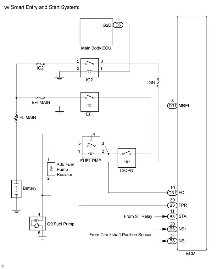
| Fuel Pump Control Circuit |
DESCRIPTION
The FUEL PUMP relay switches the fuel pump speed according to the engine conditions. The fuel pump operates when the ECM receives the starter-operating signal (STA) and crankshaft-rotating signal (NE).
The FUEL PUMP relay is turned ON while the engine is idling or operating at low load. This causes current to flow through the fuel pump resistor to the fuel pump. The fuel pump then operates at low speed.
The FUEL PUMP relay is turned OFF while the engine is cranking or operating at high load. The fuel pump then operates at normal speed.
INSPECTION PROCEDURE
PROCEDURE
- Click here
PERFORM ACTIVE TEST USING INTELLIGENT TESTER (OPERATE C/OPN RELAY)
-
Connect the intelligent tester to the DLC3.
-
Turn the ignition switch on (IG), and turn the tester on.
-
Enter the following menus: Powertrain / Engine and ECT / Active Test / Control the Fuel Pump / Speed.
-
Check the relay operation while operating it using the intelligent tester.
Standard Operating noise can be heard from the relay.
- OKClick here
- NGClick here
-
- Click here
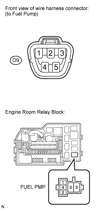
INSPECT TERMINAL VOLTAGE (FUEL PMP RELAY TERMINAL)
-
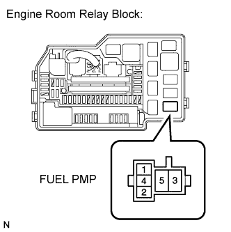
Remove the FUEL PMP relay from the engine room relay block.
-
Turn the ignition switch on (IG).
-
Measure the voltage according to the value(s) in the table below.
Standard voltage Tester Connection Switch Condition Specified Condition FUEL PMP relay terminal 2 - Body ground Ignition switch on (IG) 9 to 14 V FUEL PMP relay terminal 3 - Body ground Ignition switch on (IG) 9 to 14 V -
Reinstall the FUEL PMP relay.
- OKClick here
- NGClick here
-
- Click here
INSPECT RELAY (FUEL PMP RELAY)
-
Remove the FUEL PMP relay from the engine room relay block.
-
Measure the resistance according to the value(s) in the table below.
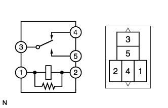
Standard resistance Tester Connection Condition Specified Condition 3 - 4 When no battery voltage is applied terminals 1 and 2 Below 1 Ω 3 - 5 When no battery voltage is applied terminals 1 and 2 10 kΩ or higher 3 - 4 When battery voltage is applied terminals 1 and 2 10 kΩ or higher 3 - 5 When battery voltage is applied terminals 1 and 2 Below 1 Ω -
Reinstall the FUEL PMP relay.
- OKClick here
- NGClick here
-
- Click here
INSPECT FUEL PUMP RESISTOR
-
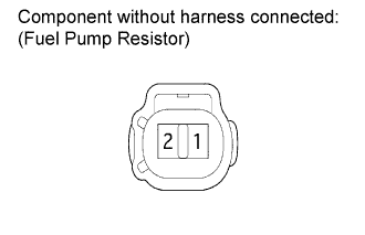
Disconnect the fuel pump resistor connector.
-
Measure the resistance according to the value(s) in the table below.
Standard resistance Tester Connection Condition Specified Condition 1 - 2 20°C (68°F) 0.30 to 0.34 Ω -
Reconnect the fuel pump resistor connector.
- OKClick here
- NGClick here
-
- Click here
CHECK HARNESS AND CONNECTOR (FUEL PUMP - FUEL PMP RELAY)
-
Check the wire harness between the FUEL PMP relay and fuel pump.
-
Remove the FUEL PMP relay from the engine room relay block.
-
Disconnect the fuel pump connector.
-
Measure the resistance according to the value(s) in the table below.
Standard resistance Tester Connection Condition Specified Condition FUEL PMP relay terminal 4 - O9-4 Always Below 1 Ω FUEL PMP relay terminal 4 or O9-4 - Body ground Always 10 kΩ or higher
-
- OKClick here
- NGClick here
-
- Click here
CHECK HARNESS AND CONNECTOR (FUEL PUP RELAY - FUEL PUMP RESISTOR)
-
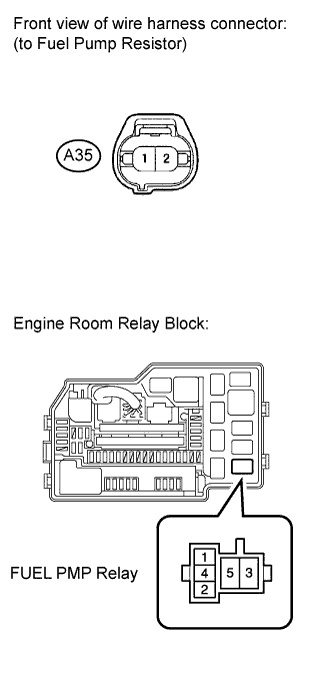
Disconnect the fuel pump resistor connector.
-
Remove the FUEL PMP relay from the engine room relay block.
-
Measure the resistance according to the value(s) in the table below.
Standard resistance (Check for open) Tester Connection Condition Specified Condition FUEL PMP relay terminal (5) - A35-1 Always Below 1 Ω Standard resistance (Check for short) Tester Connection Condition Specified Condition FUEL PMP relay terminal (5) or A35-1 - Body ground Always 10 kΩ or higher -
Reconnect the fuel pump resistor connector.
-
Reinstall the FUEL PMP relay.
- OKClick here
- NGClick here
-
- Click here
CHECK HARNESS AND CONNECTOR (FUEL PUMP RESISTOR - FUEL PUMP)
-
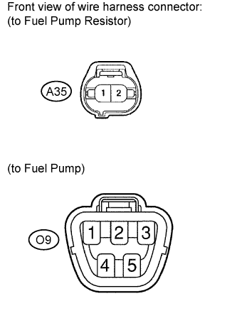
Disconnect the fuel pump resistor connector.
-
Disconnect the fuel pump connector.
-
Measure the resistance according to the value(s) in the table below.
Standard resistance (Check for open) Tester Connection Condition Specified Condition A35-2 - O9-4 Always Below 1 Ω Standard resistance (Check for short) Tester Connection Condition Specified Condition A35-2 or O9-4 - Body ground Always 10 kΩ or higher -
Reconnect the fuel pump resistor connector.
-
Reconnect the fuel pump connector.
- OKClick here
- NGClick here
-
- Click here
INSPECT FUEL PUMP
-
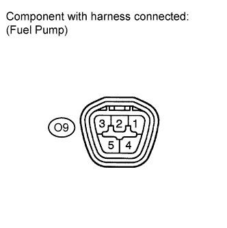
Measure the resistance of the fuel pump.
-
Measure the resistance according to the value(s) in the table below.
Standard resistance Terminal Connections Condition Specified Condition 4 - 5 20°C (68°F) 0.2 to 0.3 Ω
-
-
Check operation of the fuel pump.
-
Apply battery voltage to both terminals. Check that the pump operates.
Note:
-
These tests must be done quickly (within 10 seconds) to prevent the coil from burning out.
-
Keep the fuel pump as far away from the battery as possible.
-
Always turn ON and OFF the voltage on the battery side, not on the fuel pump side.
-
-
- OKClick here
- NGClick here
-
- Click here
CHECK ECM POWER SOURCE CIRCUIT
Tip:(Click here).
- OKClick here
- NGClick here
- Click here
INSPECT ENGINE ROOM JUNCTION BLOCK ASSEMBLY (C/OPN RELAY)
-
Inspect the C/OPN relay (Click here).
- OKClick here
- NGClick here
-
- Click here
INSPECT ECM (FC VOLTAGE)
-
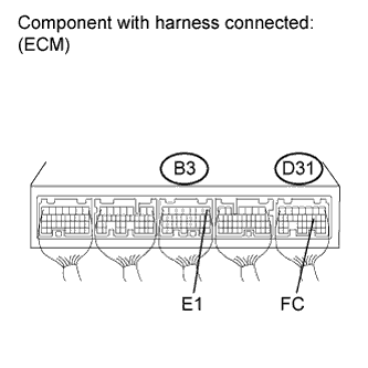
Turn the ignition switch on (IG).
-
Measure the voltage according to the value(s) in the table below.
Standard voltage Tester Connection Switch Condition Specified Condition D31-10 (FC) - B3-1 (E1) Ignition switch on (IG) 9 to 14 V
- OKClick here
- NGClick here
-
- Click here
CHECK HARNESS AND CONNECTOR (ECM - C/OPN RELAY)
-
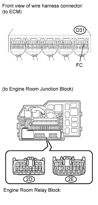
Disconnect the ECM connector.
-
Remove the engine room junction block assembly.
-
Measure the resistance according to the value(s) in the table below.
Standard resistance (Check for open) Tester Connection Condition Specified Condition D31-10 (FC) - 2D-12 (C/OPN relay terminal) Always Below 1 Ω Standard resistance (Check for short) Tester Connection Condition Specified Condition D31-10 (FC) or 2D-12 (C/OPN relay terminal) - Body ground Always 10 kΩ or higher -
Reconnect the ECM connector.
-
Reinstall the engine room junction block assembly.
- OKClick here
- NGClick here
-
- Click here
REPAIR OR REPLACE HARNESS OR CONNECTOR (FUEL PMP RELAY - C/OPN RELAY)
- Click here
REPLACE RELAY
- Click here
REPLACE FUEL PUMP RESISTORClick here
- Click here
REPAIR OR REPLACE HARNESS OR CONNECTOR
- Click here
REPLACE FUEL PUMPClick here
- Click here
REPAIR OR REPLACE ECM POWER SOURCE CIRCUIT
- Click here
REPLACE ENGINE ROOM JUNCTION BLOCKClick here
- Click here
REPLACE ECMClick here
- Click here
REPAIR OR REPLACE HARNESS OR CONNECTOR (ECM - C/OPN RELAY)
- Click here
REPLACE ENGINE ROOM JUNCTION BLOCK ASSEMBLYClick here