SFI SYSTEM, Diagnostic DTC:P0100, P0102, P0103
| DTC Code | DTC Name |
|---|---|
| P0100 | Mass or Volume Air Flow Circuit |
| P0102 | Mass or Volume Air Flow Circuit Low Input |
| P0103 | Mass or Volume Air Flow Circuit High Input |
DESCRIPTION
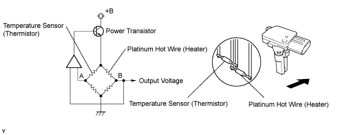
The mass air flow meter is a sensor that measures the amount of air flowing through the throttle valve. The ECM uses this information to determine the fuel injection time and to provide appropriate air fuel ratio. Inside the mass air flow meter, there is a heated platinum wire which is exposed to the flow of intake air.
By applying a specific electrical current to the wire, the ECM heats it to a specific temperature. The flow of incoming air cools both the wire and an internal thermistor, changing their resistance. To maintain a constant current value, the ECM varies the voltage applied to these components in the mass air flow meter. The voltage level is proportional to the air flow through the sensor, and the ECM uses it to calculate the intake air volume.
The circuit is constructed so that the platinum hot wire and the temperature sensor provide a bridge circuit, and the power transistor is controlled so that the potentials of A and B remain equal to maintain the predetermined temperature.
Tech Tips
When any of these DTCs are set, the ECM enters fail-safe mode. During fail-safe mode, the ignition timing is calculated by the ECM, according to the engine RPM and throttle valve position. Fail-safe mode continues until a pass condition is detected.
| DTC No. | DTC Detection Condition | Trouble Area |
|---|---|---|
| P0100 | Open or short in mass air flow meter circuit for 3 seconds (1 trip detection logic) |
|
| P0102 | Open in mass air flow meter circuit for 3 seconds (1 trip detection logic) |
|
| P0103 | Short in mass air flow meter circuit for 3 seconds (1 trip detection logic) |
|
Tech Tips
When any of these DTCs are set, check the air-flow rate by selecting the following menu items on an intelligent tester: Powertrain / Engine and ECT / Data List / MAF.
| Mass Air Flow Rate (gm/s) | Malfunction |
|---|---|
| Approximately 0.0 |
|
| 271.0 or more | Open in EVG circuit |
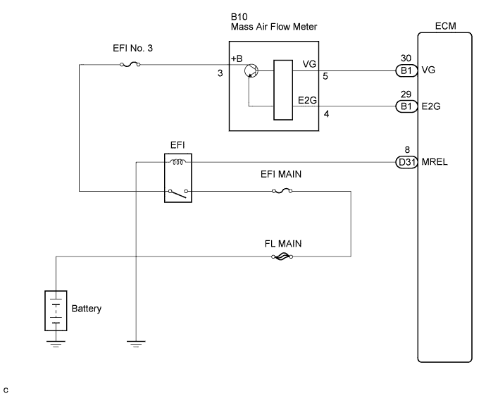
WIRING DIAGRAM
INSPECTION PROCEDURE
Tech Tips
Read freeze frame data using the intelligent tester. The ECM records vehicle and driving condition information as freeze frame data the moment a DTC is stored. When troubleshooting, freeze frame data can be helpful in determining whether the vehicle was running or stopped, whether the engine was warmed up or not, whether the air fuel ratio was lean or rich, as well as other data recorded at the time of a malfunction.
PROCEDURE
-
READ VALUE USING INTELLIGENT TESTER (MASS AIR FLOW RATE)
-
Connect the intelligent tester to the DLC3.
-
Start the engine.
-
Turn the tester on.
-
Select the following menu items: Powertrain / Engine and ECT / Data List / MAF.
-
Read the values displayed on the tester.
Result Mass Air Flow Rate (gm/s) Proceed to 0.0 A 271.0 or more B Between 1.0 and 270.0 (*1) C *1: The value must be changed when the throttle valve is open or closed.
B 
INSPECT ECM (SENSOR GROUND) Click here
C 
CHECK FOR INTERMITTENT PROBLEMS Click here
A 
-
-
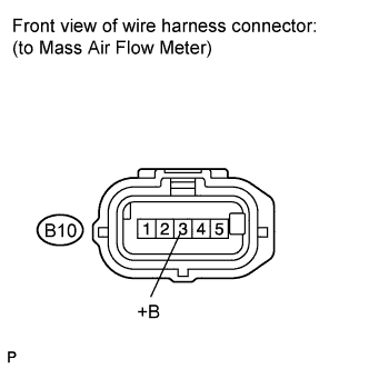
INSPECT MASS AIR FLOW METER (POWER SOURCE VOLTAGE)
-
Disconnect the mass air flow meter connector.
-
Turn the ignition switch on (IG).
-
Measure the voltage according to the value(s) in the table below.
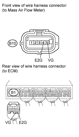
Standard voltage Tester Connection Switch Condition Specified Condition B10-3 (+B) - Body ground Ignition switch on (IG) 9 to 14 V -
Reconnect the mass air flow meter connector.
NG
INSPECT FUSE (EFI NO. 3 FUSE) Click here
OK
-
-
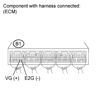
INSPECT ECM (VG VOLTAGE)
-
Start the engine.
-
Measure the voltage according to the value(s) in the table below.
Tech Tips
The transmission gear selector lever should be in the P or N position and the air conditioning switch should be turned off.
Standard voltage Tester Connection Condition Specified Condition B1-30 (VG) - B1-29 (E2G) Engine idling 0.5 to 3.0 V
NG
CHECK HARNESS AND CONNECTOR (MASS AIR FLOW METER - ECM) Click here
OK 
REPLACE ECM Click here
-
-
CHECK HARNESS AND CONNECTOR (MASS AIR FLOW METER - ECM)
-
Disconnect the mass air flow meter connector.
-
Disconnect the ECM connector.
-
Measure the resistance according to the value(s) in the table below.
Standard resistance (Check for open) Tester Connection Condition Specified Condition B10-5 (VG) - B1-30 (VG) Always Below 1 Ω B10-4 (E2G) - B1-29 (E2G) Always Below 1 Ω Standard resistance (Check for short) Tester Connection Condition Specified Condition B10-5 (VG) or B1-30 (VG) - Body ground Always 10 kΩ or higher -
Reconnect the mass air flow meter connector.
-
Reconnect the ECM connector.
NG
REPAIR OR REPLACE HARNESS OR CONNECTOR
OK
REPLACE MASS AIR FLOW METER Click here
-
-
INSPECT FUSE (EFI NO. 3 FUSE)
-
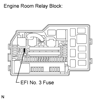
Remove the EFI No. 3 fuse from the engine room relay block.
-
Measure the resistance according to the value(s) in the table below.
Standard resistance Tester Connection Condition Specified Condition EFI No. 3 fuse Always Below 1 Ω -
Reinstall the EFI No. 3 fuse.
NG
REPLACE EFI NO. 3 FUSE
OK
REPAIR OR REPLACE HARNESS OR CONNECTOR (MASS AIR FLOW METER - EFI NO. 3 FUSE)
-
-
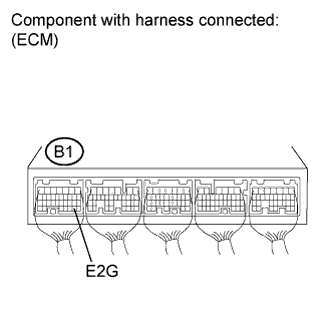
INSPECT ECM (SENSOR GROUND)
-
Measure the resistance according to the value(s) in the table below.
Standard resistance Tester Connection Condition Specified Condition B1-29 (E2G) - Body ground Always Below 1 Ω
NG
REPLACE ECM Click here
OK
-
-
CHECK HARNESS AND CONNECTOR (MASS AIR FLOW METER - ECM)
-
Disconnect the mass air flow meter connector.
-
Disconnect the ECM connector.
-
Measure the resistance according to the value(s) in the table below.
Standard resistance (Check for open) Tester Connection Condition Specified Condition B10-5 (VG) - B1-30 (VG) Always Below 1 Ω B10-4 (E2G) - B1-29 (E2G) Always Below 1 Ω Standard resistance (Check for short) Tester Connection Condition Specified Condition B10-5 (VG) or B1-30 (VG) - Body ground Always 10 kΩ or higher B10-4 (E2G) or B1-29 (E2G) - Body ground Always 10 kΩ or higher -
Reconnect the mass air flow meter connector.
-
Reconnect the ECM connector.
NG
REPAIR OR REPLACE HARNESS OR CONNECTOR
OK
REPLACE MASS AIR FLOW METER Click here
-