SFI SYSTEM, Diagnostic DTC:P0037, P0038, P0057, P0058
| DTC Code | DTC Name |
|---|---|
| P0037 | Oxygen Sensor Heater Control Circuit Low (Bank 1 Sensor 2) |
| P0038 | Oxygen Sensor Heater Control Circuit High (Bank 1 Sensor 2) |
| P0057 | Oxygen Sensor Heater Control Circuit Low (Bank 2 Sensor 2) |
| P0058 | Oxygen Sensor Heater Control Circuit High (Bank 2 Sensor 2) |
DESCRIPTION
Refer to DTC P0136 Click here.
Tech Tips
-
Sensor 2 refers to the sensor mounted behind the three-way catalytic converter and located furthest from the engine assembly.
-
When any of these DTCs are set, the ECM enters fail-safe mode. The ECM turns off the heated oxygen sensor heater in fail-safe mode. Fail-safe mode continues until the ignition switch is turned off.
-
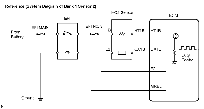
The ECM provides a pulse width modulated control circuit to adjust the current through the heater. The heated oxygen sensor heater circuit uses a relay on the B+ side of the circuit.
| DTC No. | DTC Detection Condition | Trouble Area |
|---|---|---|
| P0037 P0057 |
Heated oxygen sensor heater current is less than 0.3 A (1 trip detection logic) |
|
| P0038 P0058 |
Heated oxygen sensor heater current is more than 2 A (1 trip detection logic) |
|
Tech Tips
-
Bank 1 refers to the bank that includes cylinder No. 1.
-
Bank 2 refers to the bank that does not include cylinder No. 1.
-
Sensor 1 refers to the sensor closest to the engine assembly.
-
Sensor 2 refers to the sensor furthest away from the engine assembly.
WIRING DIAGRAM
Refer to DTC P0136 Click here
INSPECTION PROCEDURE
Tech Tips
-
If other DTCs relating to different systems that have terminal E2 as the ground terminal are output simultaneously, terminal E2 may have an open circuit.
-
Read freeze frame data using the intelligent tester. The ECM records vehicle and driving condition information as freeze frame data the moment a DTC is stored. When troubleshooting, freeze frame data can be helpful in determining whether the vehicle was running or stopped, whether the engine was warmed up or not, whether the air fuel ratio was lean or rich, as well as other data recorded at the time of a malfunction.
PROCEDURE
-
INSPECT HEATED OXYGEN SENSOR (HEATER RESISTANCE)
-
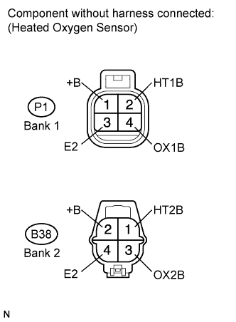
Disconnect the heated oxygen sensor connector.
-
Measure the resistance according to the value(s) in the table below.
Standard resistance Bank 1 Tester Connection Condition Specified Condition 2 (HT1B) - 1 (+B) 20°C (68°F) 11 to 16 Ω 2 (HT1B) - 3 (E2) Always 10 kΩ or higher Bank 2 Tester Connection Condition Specified Condition 1 (HT2B) - 2 (+B) 20°C (68°F) 11 to 16 Ω 1 (HT2B) - 4 (E2) Always 10 kΩ or higher -
Reconnect the heated oxygen sensor connector.
NG 
REPLACE HEATED OXYGEN SENSOR Click here
OK 
-
-
INSPECT TERMINAL VOLTAGE (HEATER POWER SOURCE)
-
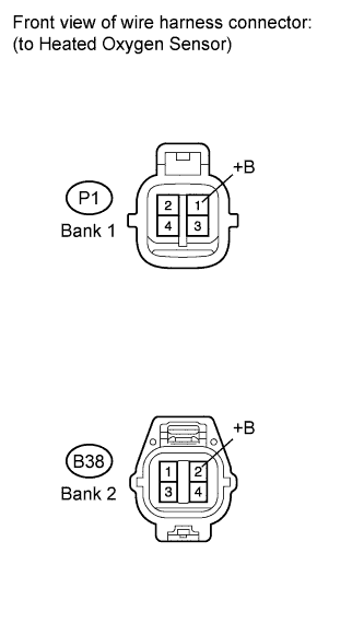
Turn the ignition switch on (IG).
-
Measure the voltage according to the value(s) in the table below.
Standard voltage Bank 1 Tester Connection Switch Condition Specified Condition P1-1 (+B) - Body ground Ignition switch on (IG) 9 to 14 V Bank 2 Tester Connection Switch Condition Specified Condition B38-2 (+B) - Body ground Ignition switch on (IG) 9 to 14 V
NG 
INSPECT FUSE (EFI NO. 3 FUSE) Click here
OK
-
-
CHECK HARNESS AND CONNECTOR (HEATED OXYGEN SENSOR - ECM)
-
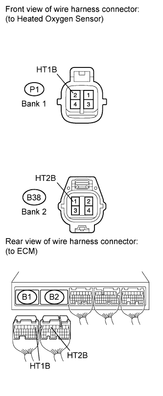
Disconnect the heated oxygen sensor connector.
-
Disconnect the ECM connector.
-
Measure the resistance according to the value(s) in the table below.
Standard resistance (Check for open) Bank 1 Tester Connection Condition Specified Condition P1-2 (HT1B) - B1-1 (HT1B) Always Below 1 Ω Bank 2 Tester Connection Condition Specified Condition B38-1 (HT2B) - B2-5 (HT2B) Always Below 1 Ω Standard resistance (Check for short) Bank 1 Tester Connection Condition Specified Condition P1-2 (HT1B) or B1-1 (HT1B) - Body ground Always Below 1 Ω Bank 2 Tester Connection Condition Specified Condition B38-1 (HT2B) or B2-5 (HT2B) - Body ground Always Below 1 Ω -
Reconnect the heated oxygen sensor connector.
-
Reconnect the ECM connector.
NG
REPAIR OR REPLACE HARNESS OR CONNECTOR
OK 
REPLACE ECM Click here
-
-
INSPECT FUSE (EFI NO. 3 FUSE)
-
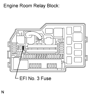
Remove the EFI No. 3 fuse from engine room relay block.
-
Measure the resistance according to the value(s) in the table below.
Standard resistance Tester Connection Condition Specified Condition EFI No. 3 fuse Always Below 1 Ω -
Reinstall the EFI No. 3 fuse.
NG
REPLACE FUSE (EFI NO. 3 FUSE)
OK
REPAIR OR REPLACE HARNESS OR CONNECTOR (EFI NO. 3 FUSE - HEATED OXYGEN SENSOR)
-