| DTC Code | DTC Name |
|---|---|
| P0365 | Camshaft Position Sensor "B" Circuit (Bank 1) |
| P0367 | Camshaft Position Sensor "B" Circuit Low Input (Bank 1) |
| P0368 | Camshaft Position Sensor "B" Circuit High Input (Bank 1) |
| P0390 | Camshaft Position Sensor "B" Circuit (Bank 2) |
| P0392 | Camshaft Position Sensor "B" Circuit Low Input (Bank 2) |
| P0393 | Camshaft Position Sensor "B" Circuit High Input (Bank 2) |
DESCRIPTION
The VVT sensor (G signal) consists of a magnet and MRE element.
The exhaust camshaft has 3 teeth on its inner circumference. When the camshaft gear rotates, the air gap changes between the protrusion on the gear and the pickup coil. The change affects the magnetic field, resulting in a change in the resistance of the MRE element. The crankshaft angle sensor plate has 34 teeth and outputs 34 signals every engine revolution. The ECM detects the standard crankshaft angle based on the G signal, actual crankshaft angle and engine speed by an NE signal.
| DTC No. | DTC Detection Condition | Trouble Area |
|---|---|---|
| P0365 P0390 |
STA ON: No VVT sensor signal to ECM while cranking for 4 seconds or more STA OFF: No VVT sensor signal to ECM with engine speed of 600 rpm or more (1 trip detection logic) |
|
| P0367 P0368 P0392 P0393 |
No VVT sensor signal to ECM with engine speed of 600 rpm or more for 5 seconds or more. (1 trip detection logic) |
|
INSPECTION PROCEDURE
Read freeze frame data using the intelligent tester. The ECM records vehicle and driving condition information as freeze frame data the moment a DTC is stored. When troubleshooting, freeze frame data can be helpful in determining whether the vehicle was running or stopped, whether the engine was warmed up or not, whether the air fuel ratio was lean or rich, as well as other data recorded at the time of a malfunction.
PROCEDURE
- Click here
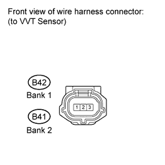
CHECK VVT SENSOR FOR EXHAUST CAMSHAFT (SENSOR POWER SOURCE)
-
Disconnect the exhaust camshaft VVT sensor connector.
-
Turn the ignition switch on (IG).
-
Measure the voltage according to the value(s) in the table below.
Standard voltage Tester Connection Switch Condition Specified Condition 3 - Body ground Ignition switch on (IG) 4.5 to 5.0 V
- OKClick here
- NGClick here
-
- Click here
CHECK HARNESS AND CONNECTOR (VVT SENSOR FOR EXHAUST CAMSHAFT - ECM)
-

Disconnect the exhaust camshaft VVT sensor connector.
-
Disconnect the ECM connector.
-
Measure the resistance according to the value(s) in the table below.
Standard resistance (Check for open) Bank 1 Tester Connection Condition Specified Condition B42-1 (VVT sensor) - B3-25 (EV1+) Always Below 1 Ω B42-2 (VVT sensor) - B3-24 (EV1-) Always Below 1 Ω Bank 2 Tester Connection Condition Specified Condition B41-1 (VVT sensor) - B3-23 (EV2+) Always Below 1 Ω B41-2 (VVT sensor) - B3-22 (EV2-) Always Below 1 Ω Standard resistance (Check for short) Bank 1 Tester Connection Condition Specified Condition B42-1 (VVT sensor) - B3-25 (EV1+) - Body ground Always 10 kΩ or higher B42-2 (VVT sensor) - B3-24 (EV1-) - Body ground Always 10 kΩ or higher Bank 2 Tester Connection Condition Specified Condition B41-1 (VVT sensor) - B3-23 (EV2+) - Body ground Always 10 kΩ or higher B41-2 (VVT sensor) - B3-22 (EV2-) - Body ground Always 10 kΩ or higher
- OKClick here
- NGClick here
-
- Click here
CHECK SENSOR INSTALLATION (VVT SENSOR FOR EXHAUST CAMSHAFT)
-
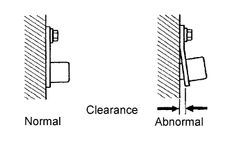
Check the VVT sensor installation condition.
OK Sensor is installed correctly.
- OKClick here
- NGClick here
-
- Click here
CHECK EXHAUST CAMSHAFT
-
Remove the cylinder head cover.
-
Check the teeth of the signal plate.
- OKClick here
- NGClick here
-
- Click here
REPLACE VVT SENSOR (FOR EXHAUST CAMSHAFT)
-
Replace the VVT sensor (Click here).
- NEXTClick here
-
- Click here
CHECK WHETHER DTC OUTPUT RECURS
-
Connect the intelligent tester to the DLC3.
-
Turn the ignition switch on (IG).
-
Turn the tester on.
-
Clear the DTCs.
-
Select the following menu items: Powertrain / Engine and ECT / Trouble Code / Pending.
-
Read the DTCs.
Result Display (DTC Output) Proceed to No output A P0365, P0352, P0353, P0354, P0355 or P0356 B Tip:If the engine does not start, replace the ECM.
-
- Click here
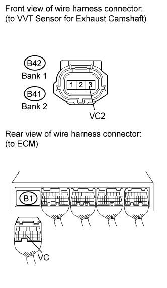
CHECK HARNESS AND CONNECTOR (VVT SENSOR - ECM)
-
Disconnect the exhaust camshaft VVT sensor connector.
-
Disconnect the ECM connector.
-
Measure the resistance according to the value(s) in the table below.
Standard resistance (Check for open) Bank 1 Tester Connection Condition Specified Condition B42-3 (VC2) - B1-23 (VC) Always Below 1 Ω Bank 2 Tester Connection Condition Specified Condition B41-3 (VC2) - B1-23 (VC) Always Below 1 Ω Standard resistance (Check for short) Bank 1 Tester Connection Condition Specified Condition B42-3 (VC2) or B1-23 (VC) - Body ground Always 10 kΩ or higher Bank 2 Tester Connection Condition Specified Condition B41-3 (VC2) or B1-23 (VC) - Body ground Always 10 kΩ or higher -
Reconnect the VVT sensor connector.
-
Reconnect the ECM connector.
- OKClick here
- NGClick here
-
- Click here
REPAIR OR REPLACE VVT SENSOR
- Click here
REPLACE EXHAUST CAMSHAFT
- Click here
REPLACE ECMClick here
- Click here
END
- Click here
REPAIR OR REPLACE HARNESS OR CONNECTOR (VVT SENSOR - ECM)
- Click here
REPAIR OR REPLACE HARNESS OR CONNECTOR