SFI SYSTEM DIAGNOSIS SYSTEM
-
EURO-OBD (EUROPEAN SPEC)

When troubleshooting Europe On-Board Diagnostic (Euro-OBD) vehicles, the vehicle must be connected to an OBD scan tool (complying with ISO 15765-4). Various data output from the vehicle's ECM can then be read.
Euro-OBD regulations require that the vehicle's on-board computer illuminates the Malfunction Indicator Lamp (MIL) on the instrument panel when the computer detects a malfunction in:
-
The emission control system/components
-
The power train control components (which affect vehicle emissions)
-
The computer
In addition, the applicable Diagnostic Trouble Codes (DTCs) prescribed by ISO 15765-4 are recorded in the ECM memory. If the malfunction does not reoccur in 3 consecutive trips, the MIL turns off automatically but the DTCs remain recorded in the ECM memory.
To check DTCs, connect the intelligent tester to the Data Link Connector 3 (DLC3) of the vehicle.
The scan tool displays DTCs, the freeze frame data and a variety of the engine data.
The DTCs and freeze frame data can be erased with the scan tool Click here.
-
-
M-OBD (EXCEPT EUROPEAN SPEC.)
When troubleshooting Multiplex On-Board Diagnostic (M-OBD) vehicle, the vehicle must be connected to the intelligent tester. Various data output from the ECM can then be read.
OBD regulations require that the vehicle's on-board computer illuminates the MIL on the instrument panel when the computer detects a malfunction in:
-
The emission control system/components
-
The power train control components (which affect vehicle emissions)
-
The computer
In addition, the applicable DTCs are recorded in the ECM memory. If the malfunction does not recur in 3 consecutive trips, the MIL turns off automatically but the DTCs remain recorded in the ECM memory.
-
-
NORMAL MODE AND CHECK MODE
The diagnosis system operates in "normal mode" during normal vehicle use. In normal mode, "2 trip detection logic" is used to ensure accurate detection of malfunctions. "Check mode" is also available to technicians as an option. In check mode, "1 trip detection logic" is used for simulating malfunction symptoms and increasing the system's ability to detected malfunctions, including intermittent malfunctions (intelligent tester only).
-
2-TRIP DETECTION LOGIC
When a malfunction is first detected, the malfunction is temporarily stored in the ECM memory (1st trip). If the same malfunction is detected again after the ignition switch is turned off and then on, the MIL will illuminate.
-
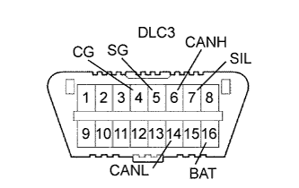
DLC3 (Data Link Connector 3)
-
Check DLC3 Click here.
-
-
INSPECT BATTERY VOLTAGE
If voltage is below 11 V, replace the battery before proceeding to the next step.
-
CHECK MIL
-
Check that the MIL illuminates when turning the ignition switch on (IG).
If the MIL does not illuminate, there is a problem in the MIL circuit Click here.
-
When the engine is started, the MIL should turn off.
-
-
ALL READINESS
Tech Tips
-
With "All Readiness" you can check whether or not the DTC judgment has been completed by using the intelligent tester.
-
You should check "All Readiness" after simulating malfunction symptoms or for validation after finishing repairs.
-
Connect the intelligent tester to the DLC3.
-
Turn the ignition switch ON.
-
Turn the tester ON.
-
Clear the DTCs Click here.
-
Perform the DC judgment driving pattern to run the DTC judgment.
-
Select the following menu items: Powertrain / Engine and ECT / Utility / All Readiness.
-
Input the DTCs to be confirmed.
-
Check the DTC judgment result.
Result Tester Display Description NORMAL
-
DTC judgment completed
-
System normal
ABNORMAL
-
DTC judgment completed
-
System abnormal
INCOMPLETE
-
DTC judgment not completed
-
You should perform driving pattern after confirming DTC enabling conditions
UNKNOWN
-
Unable to perform DTC judgment
-
Number of DTCs which do not fulfill DTC preconditions has reached ECU's memory limit
-
-