AIR OUTLET CONTROL SERVO MOTOR (for Front) INSTALLATION
-
INSTALL FRONT AIR OUTLET CONTROL SERVO MOTOR SUB-ASSEMBLY
-
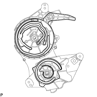
Check that the slots, links and gears of the front air outlet control servo motor sub-assembly are positioned in the correct orientation as shown in the illustration.
-
Face the contact surfaces of the front air outlet control servo motor sub-assembly and air conditioning radiator assembly for the front air outlet control servo motor sub-assembly upward.
-
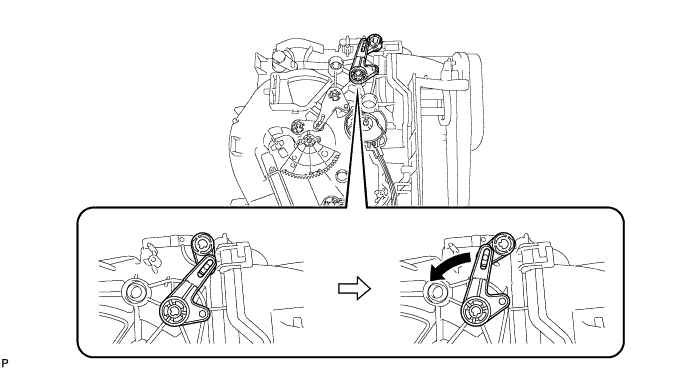
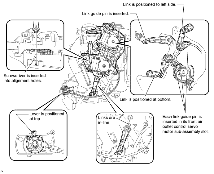
Rotate the link of the air conditioning radiator assembly all the way to the left as shown in the illustration.
-
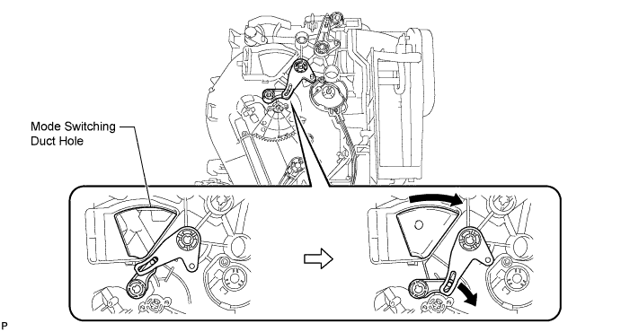
Rotate the link of the air conditioning radiator assembly to the bottom as shown in the illustration and confirm that the mode switching duct hole is fully closed.
-
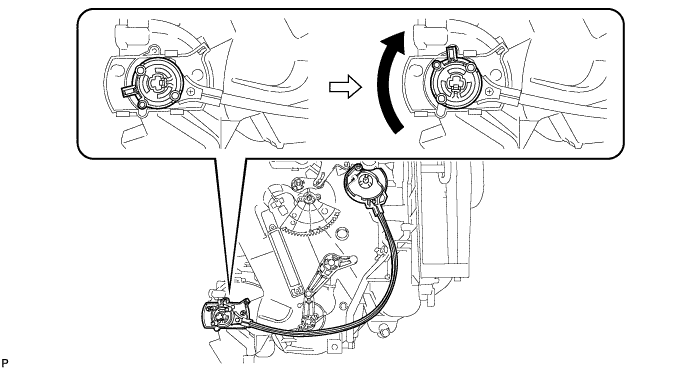
Rotate the lever of the air conditioning radiator assembly to the top as shown in the illustration.
-
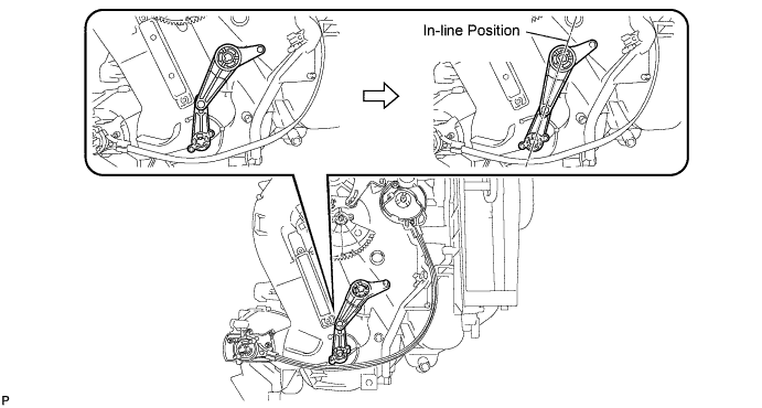
Rotate the link of the air conditioning radiator assembly to the in-line position as shown in the illustration.
-
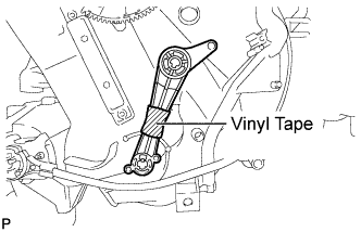
Wrap the upper and lower links with vinyl tape to hold them in the in-line position.
-
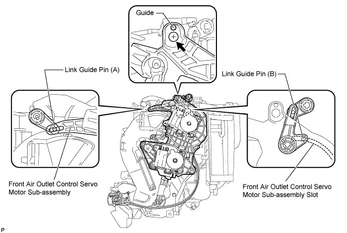
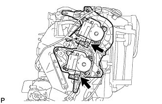
Install the link of the front air outlet control servo motor sub-assembly to the link guide pin (A) of the air conditioning radiator assembly as shown in the illustration.
-
Install the guide hole of the front air outlet control servo motor sub-assembly to the guide pin of the air conditioning radiator assembly as shown in the illustration.
-
Temporarily install the screw (up to 4 or 5 threads).
Note
-
Make sure that the link guide pin (B) is inserted in the front air outlet control servo motor sub-assembly slot.
-
Avoid tilting the front air outlet control servo motor sub-assembly during installation. This helps to prevent the guide pins from coming out of position.
-
-
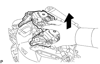
Lift the front air outlet control servo motor sub-assembly slightly to create clearance.
-
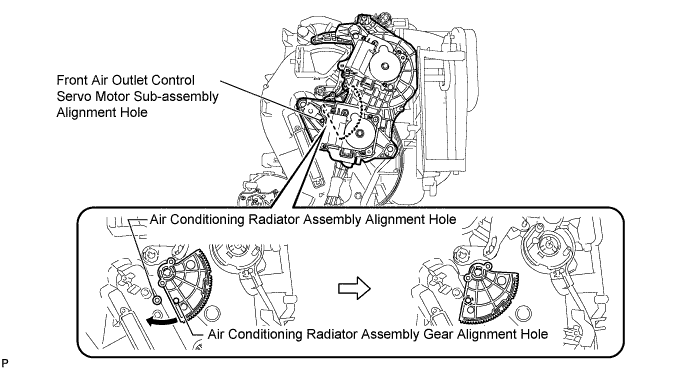
Move the air conditioning radiator assembly gear so that alignment holes of the front air outlet control servo motor sub-assembly and air conditioning radiator assembly are aligned.
-
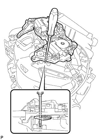
Insert a screwdriver into the aligned holes as shown in the illustration.
-
Make sure that all the links and gears are in the positions shown in the illustration.
-
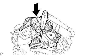
Push the loose fitting front air outlet control servo motor sub-assembly into position.
Note
-
Make sure that the front air outlet control servo motor sub-assembly is fully pushed into position.
-
After pushing the servo into position, keep it in place by holding it until the screws are installed.
Tech Tips
Push the front air outlet control servo motor sub-assembly until a click sound is heard.
-
-
Remove the screwdriver.
-
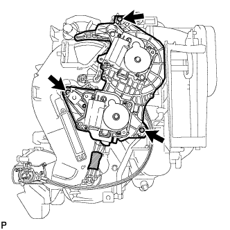
Fully install the top screw, and then install the front air outlet control servo motor sub-assembly with the 2 remaining screws.
-
Remove the vinyl tape.
-
Connect the 2 connectors.
-
-
INSTALL BLOWER ASSEMBLY
-
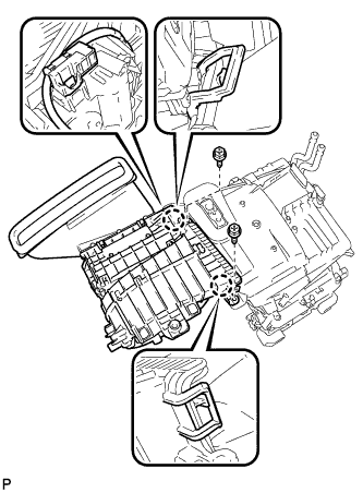
Engage the 2 claws.
-
Install the blower assembly with the 2 screws.
-
Connect the connector.
-
-
INSTALL AIR CONDITIONING UNIT
-
INITIALIZE SERVO MOTOR
-
Turn the ignition switch off.
-
Connect the intelligent tester to the DLC3.
-
Turn the ignition switch to on.
-
Press the A/C OFF switch.
-
Turn the intelligent tester on.
-
Enter the following menus: Body / Air Conditioner / Utility / Servomotor Initialization.
-
According to the intelligent tester display, select the "Next" switch.
-
According to the intelligent tester display, select the "Next" switch.
Tech Tips
During initialization, the AUTO indicator illuminates. When initialization is complete, the indicator turns off.
-
According to the intelligent tester display, select the exit to finish the initialization.
-