REAR COOLING UNIT REASSEMBLY
-
INSTALL REAR EVAPORATOR TEMPERATURE SENSOR
-
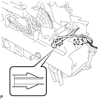
Engage the claw and install the rear evaporator temperature sensor.
-
Engage the clamp to the rear cooling unit.
-
-
INSTALL REAR EVAPORATOR SUB-ASSEMBLY
-
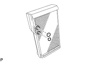
Sufficiently apply compressor oil to 2 new O-rings and the fitting surfaces. Install the 2 O-rings to the rear evaporator sub-assembly.
Compressor oil ND-OIL 8 or equivalent Note
Keep the O-rings and O-ring fitting surfaces clean from dirt or any foreign objects.
-
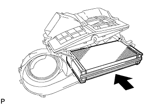
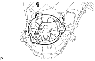
Install the rear evaporator sub-assembly as shown in the illustration.
-
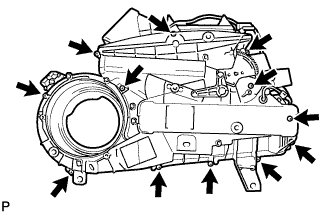
Install the 12 screws.
-
-
INSTALL REAR COOLING UNIT EXPANSION VALVE
-
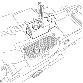
Using a 4 mm hexagon wrench, install the rear cooling unit expansion valve with the 2 hexagon bolts.
- Torque:
- 3.5 N*m { 36 kgf*cm, 31 in.*lbf }
-
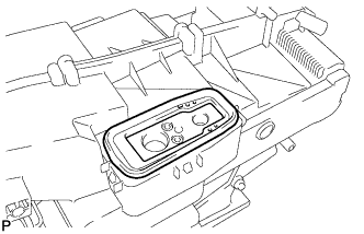
Install the grommet.
-
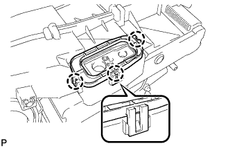
Engage the 3 claws and install the plate.
-
-
INSTALL BLOWER MOTOR CONTROLLER
-
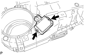
Install the blower motor controller with the 2 screws.
-
-
INSTALL REAR BLOWER MOTOR SUB-ASSEMBLY
-
Install the rear blower motor sub-assembly with the 3 screws.
-
-
INSTALL HEATER RADIATOR UNIT SUB-ASSEMBLY
-
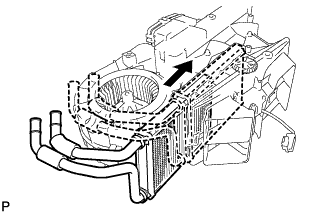
Install the heater radiator unit sub-assembly as shown in the illustration.
-
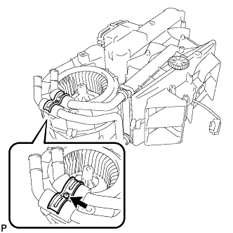
Install the clamp with the screw.
-
-
INSTALL HEATER WATER PIPE AND HOSE SUB-ASSEMBLY
-
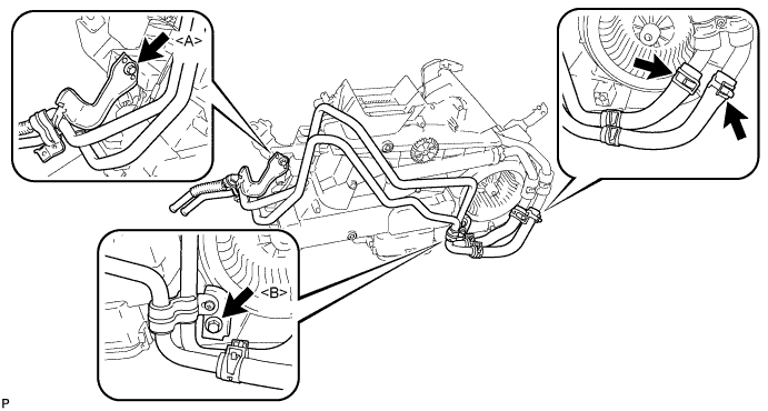
Install the screw <A>.
- Torque:
- 9.8 N*m { 100 kgf*cm, 87 in.*lbf }
-
Install the heater water pipe and hose sub-assembly with the screw <B>.
- Torque:
- 9.8 N*m { 100 kgf*cm, 87 in.*lbf }
-
Using pliers, grip the claws of the 2 clips and slide the clips to connect the heater water hose.
-
-
INSTALL REAR AIR CONDITIONING TUBE AND ACCESSORY ASSEMBLY
-
Sufficiently apply compressor oil to 2 new O-rings and the fitting surfaces of the rear air conditioning tube and accessory assembly.
Compressor oil ND-OIL 8 or equivalent -
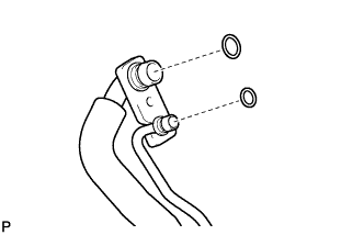
Install the 2 new O-rings on the rear air conditioning tube and accessory assembly.
-
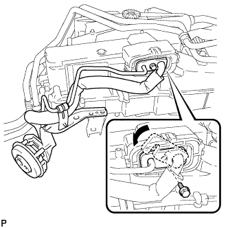
Move the hook connector in the direction indicated by the arrow in the illustration.
-
Insert the pipe joint into the fitting hole securely and tighten the bolt.
- Torque:
- 9.8 N*m { 100 kgf*cm, 87 in.*lbf }
-
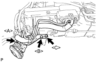
Install the bolt <A>.
- Torque:
- 9.8 N*m { 100 kgf*cm, 87 in.*lbf }
-
Install the screw <B>.
- Torque:
- 9.8 N*m { 100 kgf*cm, 87 in.*lbf }
-
Install the rear air conditioning tube and accessory assembly with the screw <C>.
- Torque:
- 9.8 N*m { 100 kgf*cm, 87 in.*lbf }
-
Install the packing.
-
-
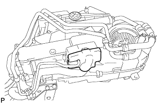
INSTALL REAR AIR OUTLET CONTROL SERVO MOTOR SUB-ASSEMBLY
-
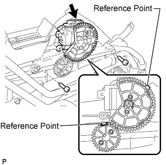
Using the reference point, install the rear air outlet control servo motor sub-assembly with the 2 screws.
-
Connect the connector.
-
-
INSTALL REAR AIR MIX CONTROL SERVO MOTOR SUB-ASSEMBLY
-
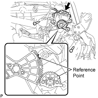
Using the reference point, install the rear air mix control servo motor sub-assembly with the 2 screws.
-
Connect the connector.
-
-
INSTALL DRAIN COOLER HOSE
-
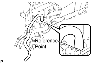
Using the reference point, install the drain cooler hose.
-