AIR OUTLET CONTROL SERVO MOTOR (for Front) INSTALLATION
-
INSTALL FRONT AIR OUTLET CONTROL SERVO MOTOR SUB-ASSEMBLY
-
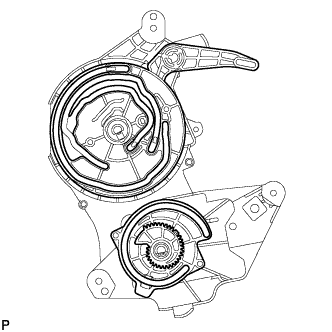
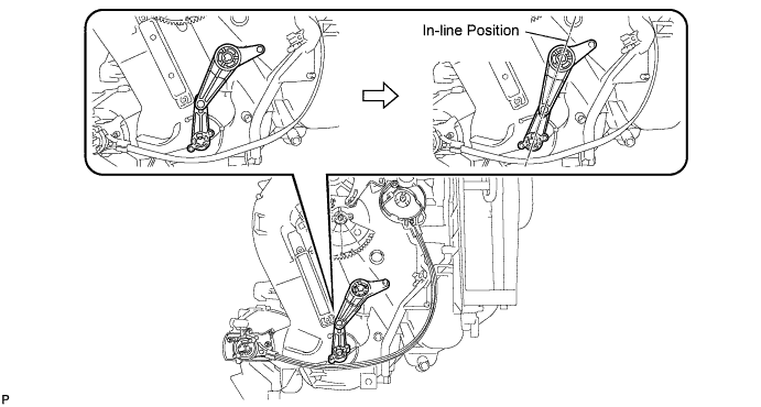
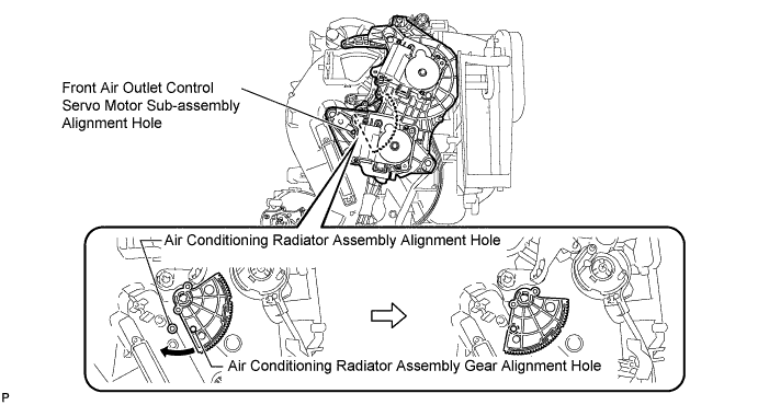
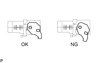
Check that the slots, links and gears of the front air outlet control servo motor sub-assembly are positioned in the correct orientation as shown in the illustration.
-
Face the contact surfaces of the front air outlet control servo motor sub-assembly and air conditioning radiator assembly for the front air outlet control servo motor sub-assembly upward.
-
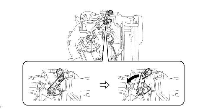
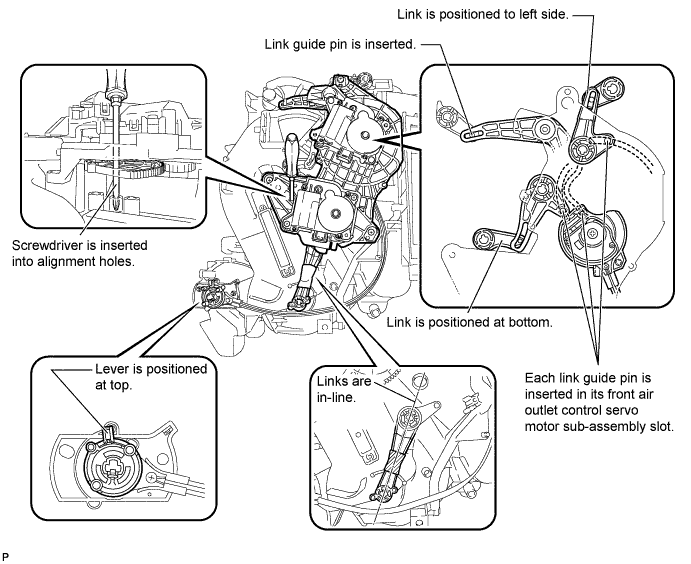
Rotate the link of the air conditioning radiator assembly all the way to the left as shown in the illustration.
-
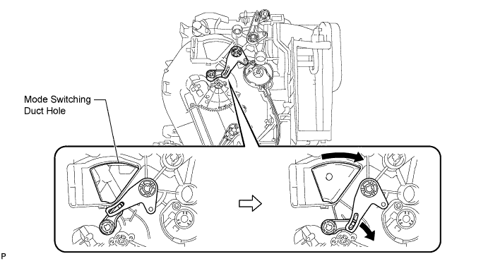
Rotate the link of the air conditioning radiator assembly to the bottom as shown in the illustration and confirm that the mode switching duct hole is fully closed.
-
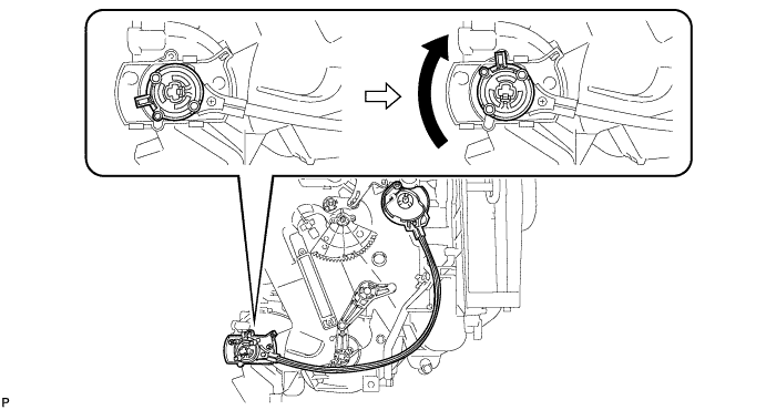
Rotate the lever of the air conditioning radiator assembly to the top as shown in the illustration.
-
Rotate the link of the air conditioning radiator assembly to the in-line position as shown in the illustration.
-
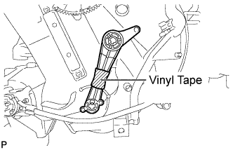
Wrap the upper and lower links with vinyl tape to hold them in the in-line position.
-
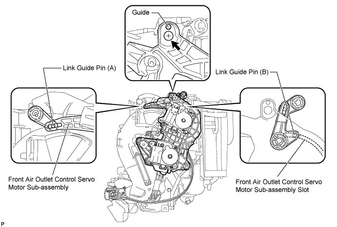
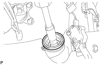
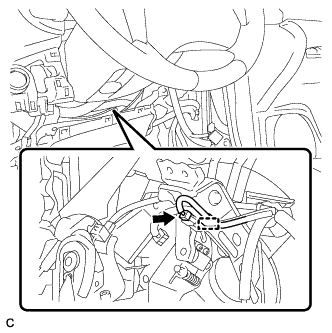
Install the link of the front air outlet control servo motor sub-assembly to the link guide pin (A) of the air conditioning radiator assembly as shown in the illustration.
-
Install the guide hole of the front air outlet control servo motor sub-assembly to the guide pin of the air conditioning radiator assembly as shown in the illustration.
-
Temporarily install the screw (up to 4 or 5 threads).
Note
-
Make sure that the link guide pin (B) is inserted in the front air outlet control servo motor sub-assembly slot.
-
Avoid tilting the front air outlet control servo motor sub-assembly during installation. This helps to prevent the guide pins from coming out of position.
-
-
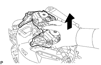
Lift the front air outlet control servo motor sub-assembly slightly to create clearance.
-
Move the air conditioning radiator assembly gear so that alignment holes of the front air outlet control servo motor sub-assembly and air conditioning radiator assembly are aligned.
-
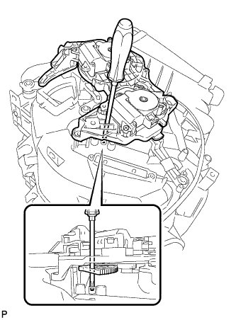
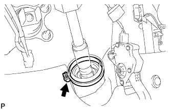
Insert a screwdriver into the aligned holes as shown in the illustration.
-
Make sure that all the links and gears are in the positions shown in the illustration.
-
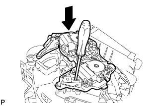
Push the loose fitting front air outlet control servo motor sub-assembly into position.
Note
-
Make sure that the front air outlet control servo motor sub-assembly is fully pushed into position.
-
After pushing the servo into position, keep it in place by holding it until the screws are installed.
Tech Tips
Push the front air outlet control servo motor sub-assembly until a click sound is heard.
-
-
Remove the screwdriver.
-
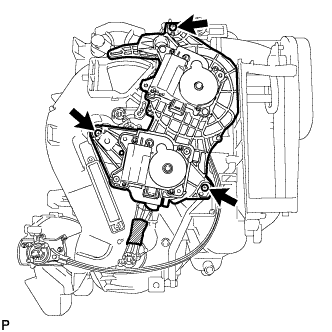
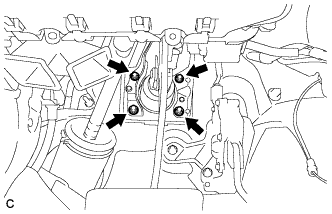
Fully install the top screw, and then install the front air outlet control servo motor sub-assembly with the 2 remaining screws.
-
Remove the vinyl tape.
-
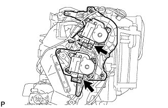
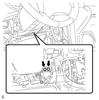
Connect the 2 connectors.
-
-
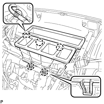
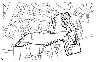
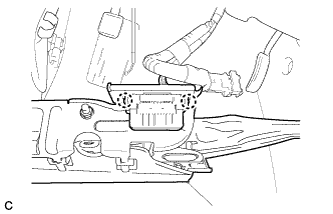
INSTALL BLOWER ASSEMBLY
-
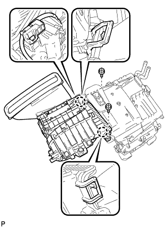
Engage the 2 claws.
-
Install the blower assembly with the 2 screws.
-
Connect the connector.
-
-
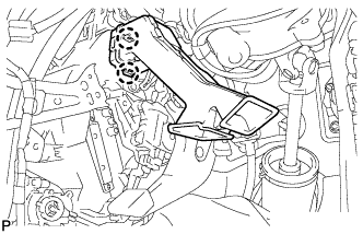
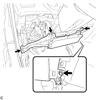
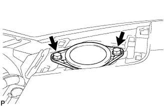
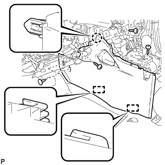
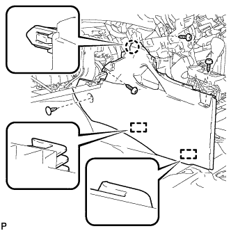
INSTALL AIR CONDITIONING UNIT
-
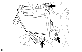
Install the air conditioning unit with the 3 bolts.
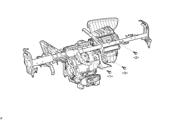
- Torque:
- 9.8 N*m { 100 kgf*cm, 87 in.*lbf }
Note
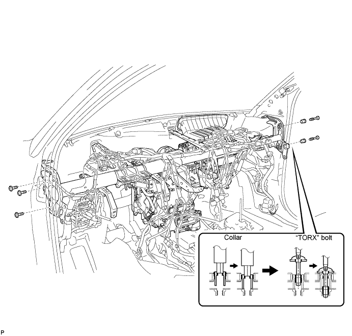
Tighten the bolts in the order shown in the illustration to install the air conditioning unit assembly.
-
-
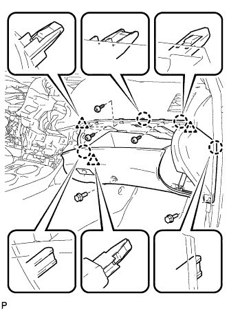
INSTALL INSTRUMENT PANEL REINFORCEMENT ASSEMBLY WITH AIR CONDITIONING UNIT (w/o PTC Heater)
-
Driver Side:
-
Using a "TORX" socket wrench (T40), install the instrument panel reinforcement assembly with the 3 "TORX" bolts.
- Torque:
- 17 N*m { 173 kgf*cm, 13 ft.*lbf }
-
-
Passenger Side:
-
Using a 12 mm hexagon wrench, adjust the position of the 2 collars.
- Torque:
- 6.0 N*m { 61 kgf*cm, 53 in.*lbf }
-
Using a "TORX" socket wrench (T40), install the instrument panel reinforcement assembly with the 2 "TORX" bolts.
- Torque:
- 20 N*m { 204 kgf*cm, 15 ft.*lbf }
-
-
Install the 2 bolts and 2 caps to the engine compartment side.
- Torque:
- 20 N*m { 204 kgf*cm, 15 ft.*lbf }
-
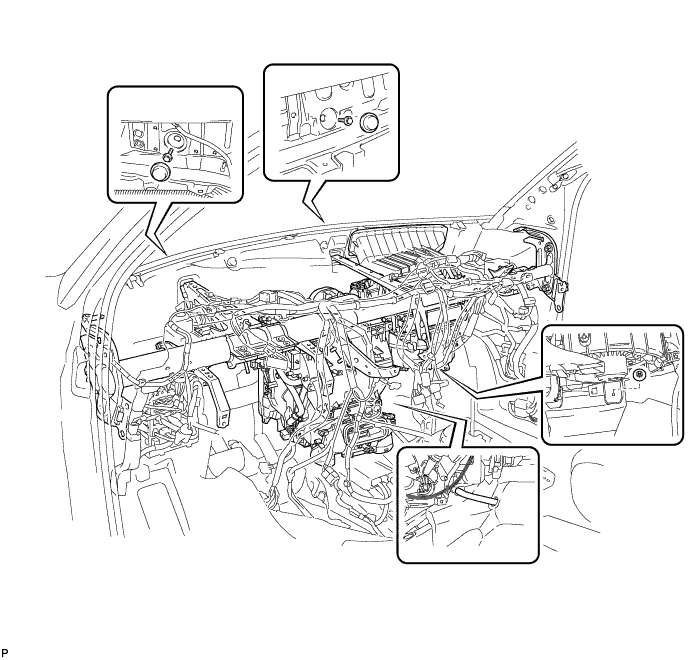
Install the instrument panel reinforcement assembly with air conditioning unit with the nut.
- Torque:
- 9.8 N*m { 100 kgf*cm, 87 in.*lbf }
-
Engage the cooler drain hose.
-
Connect the blower motor connector.
-
Install the 2 nuts and bolt.
-
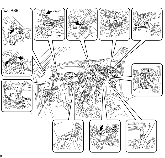
Connect each connector.
-
Connect the 2 earth wires with the 2 bolts <A>.
- Torque:
- 8.4 N*m { 86 kgf*cm, 74 in.*lbf }
-
Engage each clamp.
-
-
INSTALL INSTRUMENT PANEL REINFORCEMENT ASSEMBLY WITH AIR CONDITIONING UNIT (w/ PTC Heater)
-
Driver Side:
-
Using a "TORX" socket wrench (T40), install the instrument panel reinforcement assembly with the 3 "TORX" bolts.
- Torque:
- 17 N*m { 173 kgf*cm, 13 ft.*lbf }
-
-
Passenger Side:
-
Using a 12 mm hexagon wrench, adjust the position of the 2 collars.
- Torque:
- 6.0 N*m { 61 kgf*cm, 53 in.*lbf }
-
Using a "TORX" socket wrench (T40), install the instrument panel reinforcement assembly with the 2 "TORX" bolts.
- Torque:
- 20 N*m { 204 kgf*cm, 15 ft.*lbf }
-
-
Install the 2 bolts and 2 caps to the engine compartment side.
- Torque:
- 20 N*m { 204 kgf*cm, 15 ft.*lbf }
-
Install the instrument panel reinforcement assembly with air conditioning unit with the nut.
- Torque:
- 9.8 N*m { 100 kgf*cm, 87 in.*lbf }
-
Engage the cooler drain hose.
-
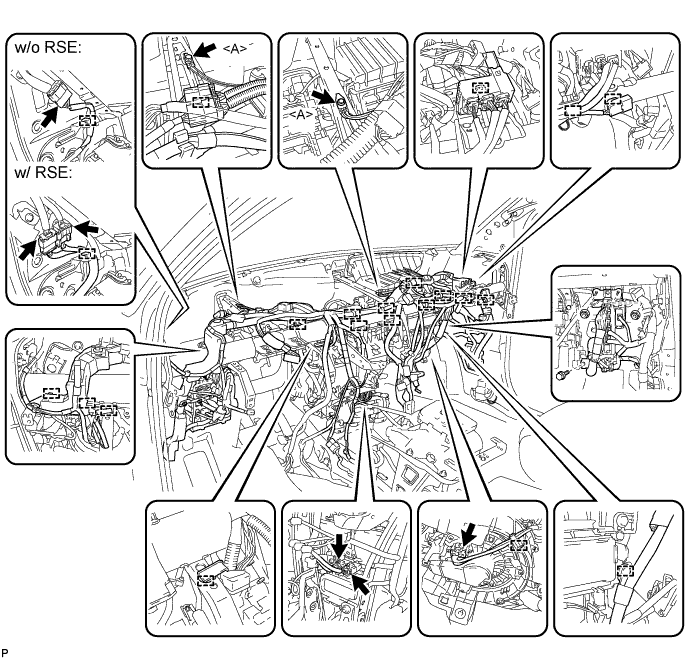
Connect the 2 quick heater connectors.
-
Connect the blower motor connector.
-
Install the 2 nuts and bolt.
-
Connect each connector.
-
Connect the 2 earth wires with the 2 bolts <A>.
- Torque:
- 8.4 N*m { 86 kgf*cm, 74 in.*lbf }
-
Engage each clamp.
-
-
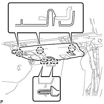
INSTALL NO. 1 INSTRUMENT PANEL BRACE SUB-ASSEMBLY
-
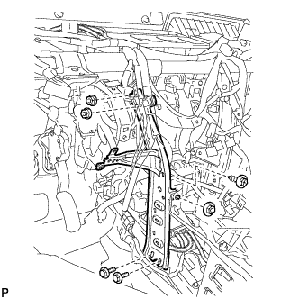
Install the 3 nuts.
-
Install the 2 bolts.
-
Install the No. 1 instrument panel brace sub-assembly with the screw.
- Torque:
- 9.8 N*m { 100 kgf*cm, 87 in.*lbf }
-
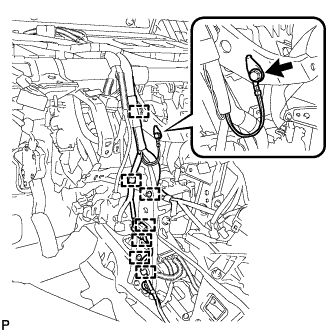
Engage each clamp.
-
Connect the earth wire with the bolt.
- Torque:
- 8.4 N*m { 86 kgf*cm, 74 in.*lbf }
-
-
INSTALL NO. 2 INSTRUMENT PANEL BRACE SUB-ASSEMBLY
-
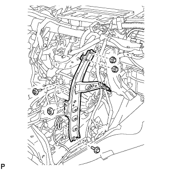
Install the 3 nuts.
-
Install the bolt.
-
Install the No. 2 instrument panel brace sub-assembly with the screw.
- Torque:
- 9.8 N*m { 100 kgf*cm, 87 in.*lbf }
-
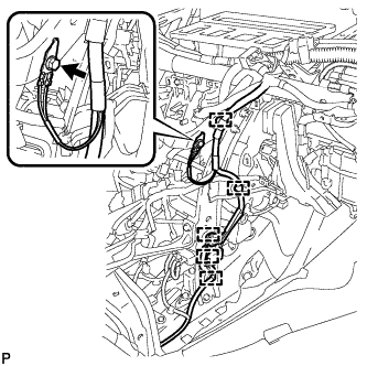
Engage each clamp.
-
Connect the earth wire with the bolt.
- Torque:
- 8.4 N*m { 86 kgf*cm, 74 in.*lbf }
-
-
INSTALL CENTER HEATER TO REGISTER DUCT
-
Engage the 4 claws and install the center heater to register duct.
-
Engage the clamp.
-
-
INSTALL NO. 1 CONSOLE BOX DUCT (w/o Rear Air Conditioning System)
-
Install the clip and the No. 1 console box duct.
-
-
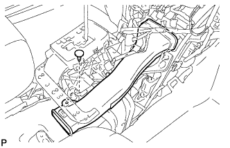
INSTALL REAR NO. 3 AIR DUCT
-
Engage the 2 claws and install the rear No. 3 air duct.
-
Install the clip.
-
Engage the claw and install the floor carpet.
-
-
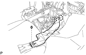
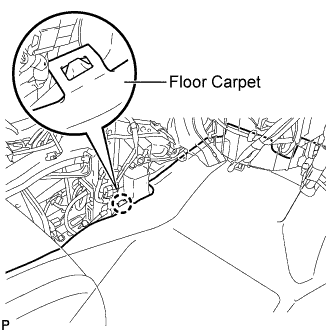
INSTALL REAR NO. 1 AIR DUCT
-
Engage the 2 claws and install the rear No. 1 air duct.
-
Install the clip.
-
Engage the clamp.
-
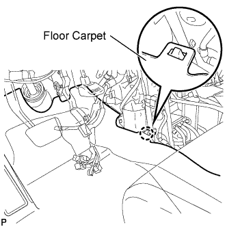
Engage the claw and install the floor carpet.
-
-
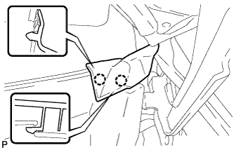
INSTALL AIR CONDITIONING AMPLIFIER ASSEMBLY
-
Install the air conditioning amplifier assembly with the 2 screws.
-
Connect each connector.
-
-
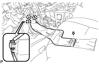
INSTALL ECM (for RHD)
-
Install the 2 nuts, bolt and ECM.
- Torque:
- 8.0 N*m { 82 kgf*cm, 71 in.*lbf }
-
Install the wire harness clamp.
-
Connect the 5 ECM connectors.
-
Connect the harness connector (LHD).
-
-
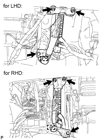
INSTALL POWER STEERING ECU ASSEMBLY (for LHD)
-
Install the power steering ECU assembly with the 3 nuts.
- Torque:
- 14 N*m { 143 kgf*cm, 10 ft.*lbf }
-
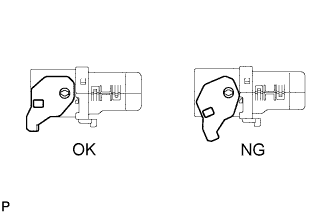
Check that the connector lever is at the fully unlocked position before installation.
Note
If the lever has been lifted out of the fully unlocked position, it may cause a faulty connection.
-
Connect the 4 connectors to the power steering ECU assembly.
-
Lightly pull on the connector and check that the connector does not disconnect.
-
-
INSTALL POWER STEERING ECU ASSEMBLY (for RHD)
-
Install the power steering ECU assembly with the 3 nuts.
- Torque:
- 14 N*m { 143 kgf*cm, 10 ft.*lbf }
-
Check that the connector lever is at the fully unlocked position before installation.
Note
If the lever has been lifted out of the fully unlocked position, it may cause a faulty connection.
-
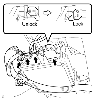
Connect the 4 connectors to the power steering ECU assembly.
-
Lightly pull on the connector and check that the connector will not be disconnected.
-
Install the wire harness clamp to the power steering ECU assembly.
-
-
CONNECT INSTRUMENT PANEL JUNCTION BLOCK ASSEMBLY
-
Connect the instrument panel junction block assembly with the 3 nuts.
- Torque:
- 8.4 N*m { 86 kgf*cm, 74 in.*lbf }
-
-
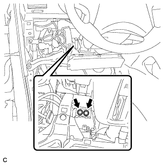
INSTALL STEERING COLUMN ASSEMBLY (for LHD)
-
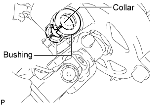
Check that the 2 bushings are securely installed to the steering column assembly.
Tech Tips
If the bushings are missing or damaged, replace the steering column assembly with a new one.
-
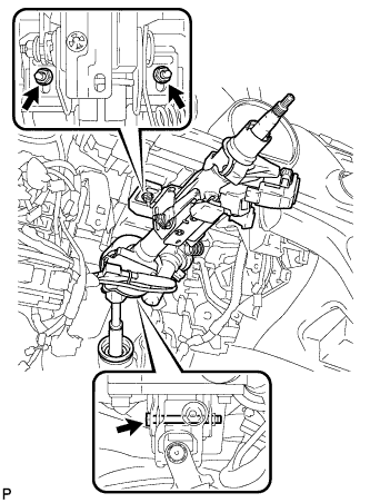
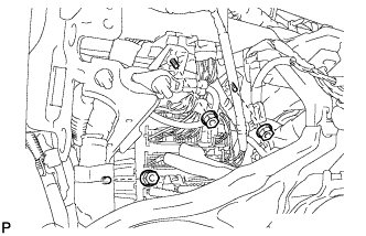
Install the steering column assembly with the bolt and 2 nuts.
- Torque:
- Bolt
- 36 N*m { 367 kgf*cm, 27 ft.*lbf }
- Nut
- 25 N*m { 255 kgf*cm, 18 ft.*lbf }
Note
There are two different bolt sizes (12 mm (0.472 in.) or 14 mm (0.551 in.)) available.
-
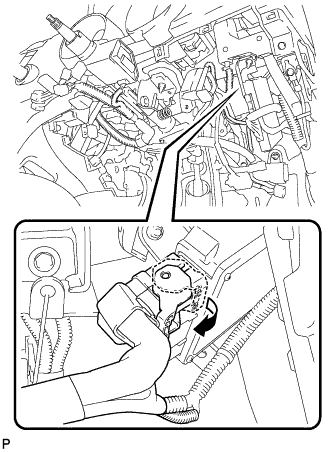
Connect the connectors and engage the wire harness clamps to the steering column assembly.
-
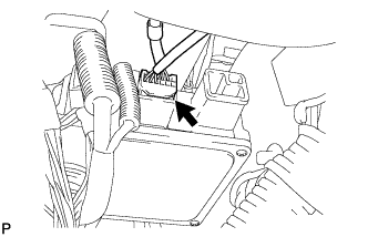
Connect the connector to the power steering ECU assembly.
-
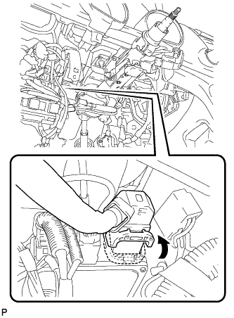
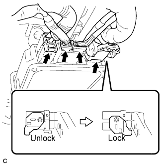
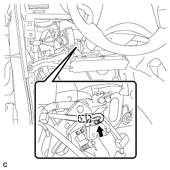
Connect the connector to the power steering ECU assembly.
Tech Tips
As shown in the illustration, securely return the lock lever to its original position to connect the connector.
-
-
INSTALL STEERING COLUMN ASSEMBLY (for RHD)
-
Check that the 2 bushings are securely installed to the steering column assembly.
Tech Tips
If the bushings are missing or damaged, replace the steering column assembly with a new one.
-
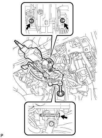
Install the steering column assembly with the bolt and 2 nuts.
- Torque:
- Bolt
- 36 N*m { 367 kgf*cm, 27 ft.*lbf }
- Nut
- 25 N*m { 255 kgf*cm, 18 ft.*lbf }
Note
There are two different bolt sizes (12 mm (0.472 in.) or 14 mm (0.551 in.)) available.
-
Connect the connectors and engage the wire harness clamps to the steering column assembly.
-
Connect the connector to the power steering ECU assembly.
-
Connect the connector to the power steering ECU assembly.
Tech Tips
As shown in the illustration, securely return the lock lever to its original position to connect the connector.
-
-
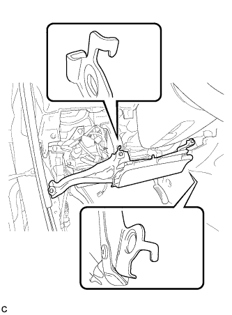
CONNECT STEERING INTERMEDIATE SHAFT SUB-ASSEMBLY
-
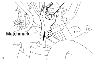
Align the matchmarks on the steering intermediate shaft sub-assembly and the power steering link assembly.
-
Install a new bolt.
- Torque:
- 35 N*m { 360 kgf*cm, 26 ft.*lbf }
-
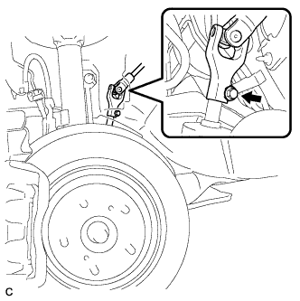
Install the steering intermediate shaft sub-assembly to the steering column hole shield.
-
Tighten the bolt.
-
-
INSTALL NO. 1 AIR DUCT SUB-ASSEMBLY (for LHD)
-
Engage the 2 claws to install the No. 1 air duct sub-assembly.
-
-
INSTALL NO. 1 AIR DUCT SUB-ASSEMBLY (for RHD)
-
Engage the 2 claws to install the No. 1 air duct sub-assembly.
-
-
INSTALL DRIVER SIDE KNEE AIRBAG ASSEMBLY
-
Check that the ignition switch is off.
-
Check that the battery negative (-) cable is disconnected.
CAUTION:
Wait for at least 90 seconds after disconnecting the cable to prevent airbag deployment.
-
Install the DLC3 to the driver side knee airbag assembly with the 2 claws.
-
Connect the connector to the driver side knee airbag assembly.
Note
When handling the airbag connector, take care not to damage the airbag wire harness.
-
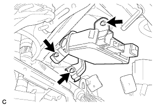
Support the driver side knee airbag assembly with one hand as shown in the illustration.
-
Temporarily install the driver side knee airbag assembly with the 2 hooks.
-
Install the driver side knee airbag assembly with the 4 bolts.
- Torque:
- 10 N*m { 102 kgf*cm, 7 ft.*lbf }
-
-
INSTALL BRAKE PEDAL SUPPORT SUB-ASSEMBLY (for LHD)
-
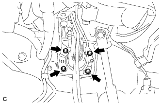
Install the brake pedal support sub-assembly with the 4 nuts.
- Torque:
- 13 N*m { 132 kgf*cm, 10 ft.*lbf }
-
Install the brake pedal support sub-assembly to the instrument panel reinforcement with the 2 bolts.
- Torque:
- 35 N*m { 357 kgf*cm, 26 ft.*lbf }
-
Connect the brake pedal load sensing switch connector and engage the clamp.
-
-
INSTALL BRAKE PEDAL SUPPORT SUB-ASSEMBLY (for RHD)
-
Install the brake pedal support sub-assembly with the 4 nuts.
- Torque:
- 13 N*m { 132 kgf*cm, 10 ft.*lbf }
-
Install the brake pedal support sub-assembly to the instrument panel reinforcement with the 2 bolts.
- Torque:
- 35 N*m { 357 kgf*cm, 26 ft.*lbf }
-
Connect the brake pedal load sensing switch connector and engage the clamp.
-
-
CONNECT BRAKE MASTER CYLINDER PUSH ROD CLEVIS
-
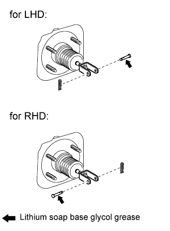
Apply lithium soap base glycol grease to the push rod pin.
-
Connect the brake master cylinder push rod clevis to the brake pedal with the push rod pin, and install a new clip as shown in the illustration.
-
-
INSTALL BRAKE PEDAL RETURN SPRING
-
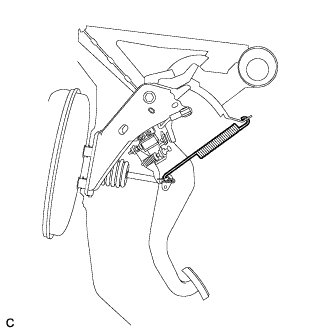
Install the brake pedal return spring between the instrument panel reinforcement and brake master cylinder push rod clevis.
-
-
INSTALL STOP LIGHT SWITCH ASSEMBLY
-
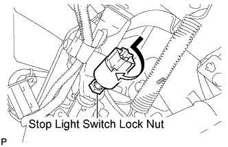
Temporarily install the stop light switch assembly with the stop light switch lock nut.
-
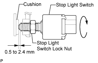
Turn the stop light switch assembly so that the clearance between the nut end and stop light switch cushion is between 0.5 to 2.4 mm (0.020 to 0.095 in.).
-
Tighten the stop light switch lock nut.
- Torque:
- 17 N*m { 173 kgf*cm, 12 ft.*lbf }
-
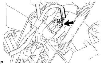
Connect the connector.
-
-
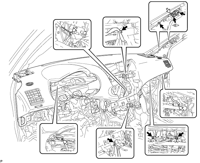
INSTALL INSTRUMENT PANEL SAFETY PAD ASSEMBLY (for Pole Antenna Type)
-
Engage the 5 claws.
Note
Do not allow the wire harness to get caught in the claws.
-
Install the 2 bolts <D> and nut <H>.
-
Install the 2 clips.
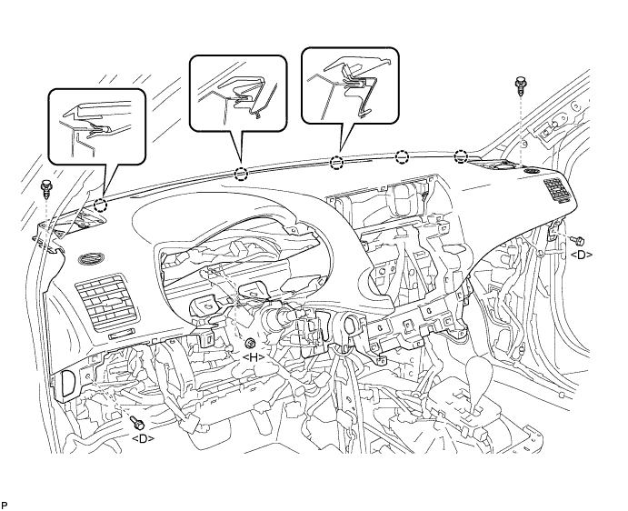
-
Engage each clamp.
-
Install the 2 passenger airbag bolts <A>.
- Torque:
- 20 N*m { 204 kgf*cm, 15 ft.*lbf }
-
Install the bolt <E>.
-
Connect each connector and install the instrument panel safety pad assembly.
-
-
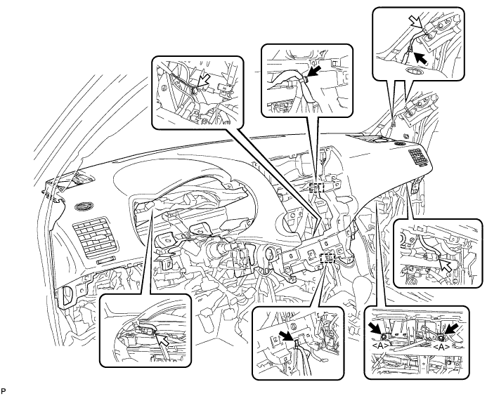
INSTALL INSTRUMENT PANEL SAFETY PAD ASSEMBLY (for Glass Antenna Type)
-
Engage the 5 claws.
Note
Do not allow the wire harness to get caught in the claws.
-
Install the 2 bolts <D> and nut <H>.
-
Install the 2 clips.
-
Engage each clamp.
-
Install the 2 passenger airbag bolts <A>.
- Torque:
- 20 N*m { 204 kgf*cm, 15 ft.*lbf }
-
Connect each connector and install the instrument panel safety pad assembly.
-
-
CONNECT INSTRUMENT PANEL WIRE ASSEMBLY
-
Check that the ignition switch is off.
-
Check that the battery negative (-) terminal is disconnected.
CAUTION:
Wait for at least 90 seconds after disconnecting the cable to prevent airbag deployment.
-
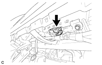
Connect the connector.
-
-
INSTALL FRONT NO. 2 SPEAKER ASSEMBLY (for LH Side)
-
Connect the connector.
-
Install the front No. 2 speaker assembly with the 2 bolts.
-
-
INSTALL NO. 1 INSTRUMENT PANEL SPEAKER PANEL SUB-ASSEMBLY
-
Engage the 2 guides.
-
Engage the 2 claws and 2 clips, and install the No. 1 instrument panel speaker panel sub-assembly.
-
-
INSTALL FRONT NO. 2 SPEAKER ASSEMBLY (for RH Side)
Tech Tips
Use the same procedures for the RH side and the LH side.
-
INSTALL NO. 2 INSTRUMENT PANEL SPEAKER PANEL SUB-ASSEMBLY
-
Engage the 2 guides.
-
Engage the 2 claws and 2 clips, and install the No. 2 instrument panel speaker panel sub-assembly.
-
-
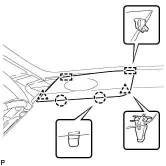
INSTALL FRONT PILLAR GARNISH RH
-
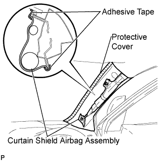
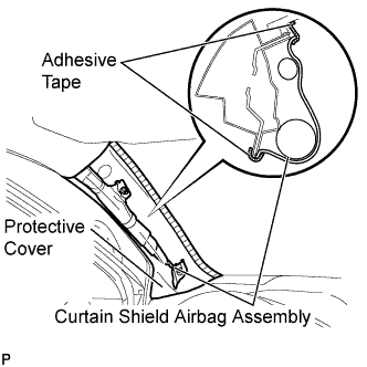
Remove the protective cover.
-
Install a new clip <A> on the front pillar garnish RH.
-
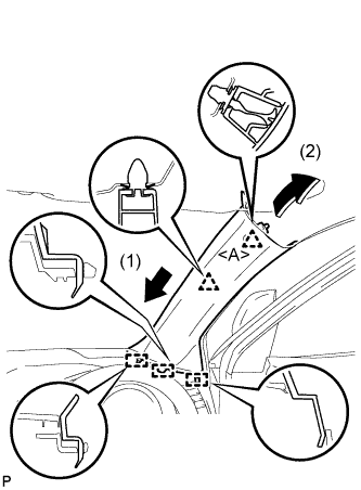
Engage the 3 guides and 2 clips, then install the front pillar garnish RH.
-
-
CONNECT FRONT DOOR OPENING TRIM WEATHERSTRIP RH
-
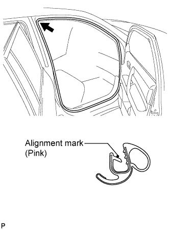
Align the alignment mark (pink) on the weatherstrip with the protruding portion on the body indicated by the arrow in the illustration, and install the front door opening trim weatherstrip RH.
Note
After installation, check that the corners fit correctly.
-
-
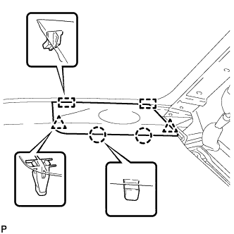
INSTALL FRONT PILLAR GARNISH LH
-
Remove the protective cover.
-
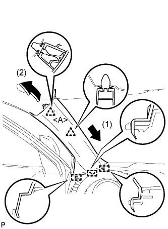
Install a new clip <A> on the front pillar garnish LH.
-
Engage the 3 guides and 2 clips, then install the front pillar garnish LH.
-
-
CONNECT FRONT DOOR OPENING TRIM WEATHERSTRIP LH
-
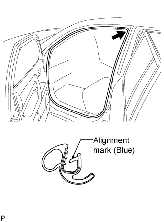
Align the alignment mark (blue) on the weatherstrip with the protruding portion on the body indicated by the arrow in the illustration, and install the front door opening trim weatherstrip LH.
Note
After installation, check that the corners fit correctly.
-
-
INSTALL ENGINE SWITCH (w/ Smart Entry and Start System)
-
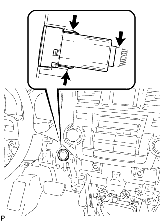
Engage the 2 claws to install the switch.
-
Connect the switch connector.
-
-
INSTALL FRONT NO. 2 CONSOLE BOX INSERT (for LHD)
-
Engage the claw and 2 guides.
-
Install the front No. 2 console box insert with the 3 screws <F> and clip.
-
-
INSTALL FRONT NO. 2 CONSOLE BOX INSERT (for RHD)
-
Engage the claw and 2 guides.
-
Install the front No. 2 console box insert with the 3 screws <F> and clip.
-
-
INSTALL FRONT NO. 1 CONSOLE BOX INSERT (for LHD)
-
Engage the claw and 2 guides.
-
Install the front No. 1 console box insert with the 3 screws <F> and 2 clips.
-
-
INSTALL FRONT NO. 1 CONSOLE BOX INSERT (for RHD)
-
Engage the claw and 2 guides.
-
Install the front No. 1 console box insert with the 3 screws <F> and clip.
-
-
INSTALL CONSOLE BOX ASSEMBLY (w/o Rear Air Conditioning System)
-
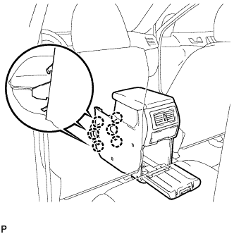
Engage the 6 claws.
-
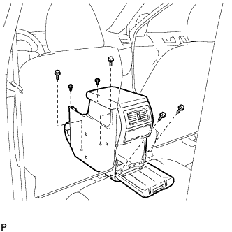
Install the console box assembly with the 4 bolts and 2 screws.
-
-
INSTALL CONSOLE BOX ASSEMBLY (w/ Rear Air Conditioning System)
-
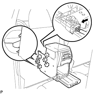
Engage the 6 claws.
-
Connect the connector.
-
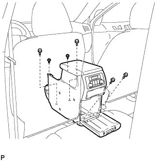
Install the console box assembly with the 4 bolts and 2 screws.
-
-
INSTALL LOWER REAR CONSOLE BOX
-
Install the lower rear console box.
-
-
INSTALL NO. 2 CONSOLE BOX DUCT (w/o Rear Air Conditioning System)
-
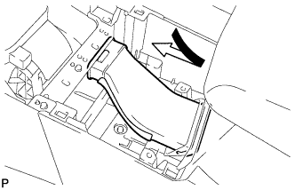
Install the No. 2 console box duct as shown in the illustration.
-
-
INSTALL UPPER CONSOLE PANEL SUB-ASSEMBLY
-
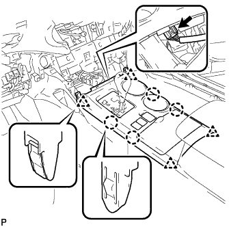
Connect the connector.
-
Engage the 4 claws and 4 clips, and install the upper console panel sub-assembly.
-
-
INSTALL LOWER INSTRUMENT PANEL SUB-ASSEMBLY
-
Connect each connector and clamp.
-
Engage the 4 claws and 3 clips.
-
Install the lower instrument panel sub-assembly with the 2 bolts <B> and 3 screws <F>.
-
-
INSTALL NO. 2 INSTRUMENT PANEL UNDER COVER SUB-ASSEMBLY
-
Engage the 2 guides.
-
Engage the 3 claws and install the No. 2 instrument panel under cover sub-assembly.
-
-
INSTALL COWL SIDE TRIM SUB-ASSEMBLY RH
Tech Tips
Use the same procedure for the RH side and the LH side.
-
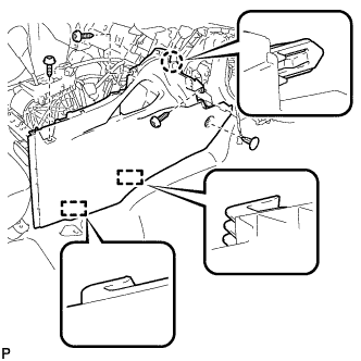
INSTALL FRONT DOOR SCUFF PLATE RH
Tech Tips
Use the same procedure for the RH side and the LH side.
-
INSTALL LOWER INSTRUMENT PANEL FINISH PANEL SUB-ASSEMBLY (for Manual Air Conditioning System)
-

Connect the hood lock control cable assembly.
-
Connect each connector.
-
Engage the 3 claws and 10 clips.
-
Install the lower instrument panel finish panel sub-assembly with the 2 bolts <B>.
-
-
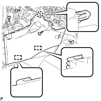
INSTALL LOWER INSTRUMENT PANEL FINISH PANEL SUB-ASSEMBLY (for Automatic Air Conditioning System)
-

Connect the hood lock control cable assembly.
-
Connect each connector and the aspirator duct.
-

Engage the 3 claws and 10 clips.
-
Install the lower instrument panel finish panel sub-assembly with the 2 bolts <B>.
-
-
INSTALL COWL SIDE TRIM SUB-ASSEMBLY LH
-

Engage the claw and clip, install the cowl side trim sub-assembly LH.
-
Install the clip.
-
-
INSTALL FRONT DOOR SCUFF PLATE LH
-

Engage the guide and the 8 claws, and install the front door scuff plate LH.
-
-
INSTALL RADIO RECEIVER ASSEMBLY WITH BRACKET (w/o Navigation System)
-
Connect each connector.
-
Engage the 4 clips.
-
Install the radio receiver assembly with bracket with the 4 bolts.
-
-
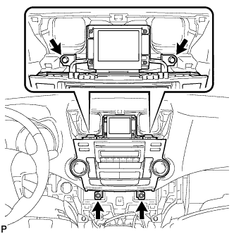
INSTALL NAVIGATION RECEIVER ASSEMBLY WITH BRACKET (w/ Navigation System)
-
Connect each connector.
-
Engage the 4 clips.
-
Install the navigation receiver assembly with bracket with the 4 bolts.
-
-
INSTALL INTEGRATION CONTROL AND PANEL ASSEMBLY WITH BRACKET (w/o Radio Receiver)
-
Connect each connector.
-
Engage the 4 clips.
-
Install the integration control and panel assembly with bracket with the 4 bolts <D>.
-
-
INSTALL HEATER CONTROL AND ACCESSORY ASSEMBLY (for Manual Air Conditioning System)
-
Connect the connector.
-

Engage the 4 clips and install the heater control and accessory assembly.
-
-
INSTALL AIR CONDITIONING CONTROL ASSEMBLY (for Automatic Air Conditioning System)
-
Connect the connector.
-
Engage the 4 clips and install the air conditioning control assembly.
-
-
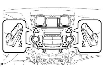
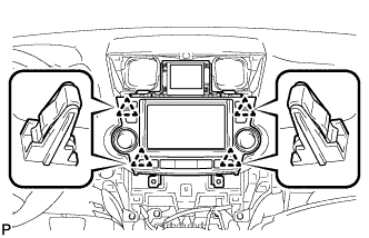
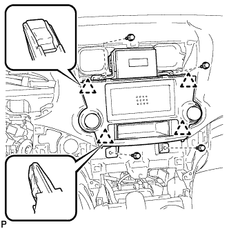
INSTALL CENTER INSTRUMENT CLUSTER FINISH PANEL ASSEMBLY (w/o Smart Entry and Start System)
-

Apply protective tape to the areas shown in the illustration.
-
Connect each connector.
-
Engage the 10 claws and 8 clips, and install the center instrument cluster finish panel assembly.
Note
Do not the damage the instrument panel safety pad assembly and lower instrument panel finish panel sub-assembly.
-
-
INSTALL CENTER INSTRUMENT CLUSTER FINISH PANEL ASSEMBLY (w/ Smart Entry and Start System)
-
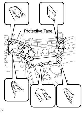
Apply protective tape to the areas shown in the illustration.
-
Connect each connector.
-
Engage the 10 claws and 8 clips, and install the center instrument cluster finish panel assembly.
Note
Do not the damage the instrument panel safety pad assembly and lower instrument panel finish panel sub-assembly.
-
-
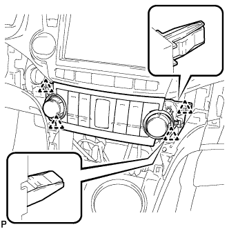
INSTALL CENTER INSTRUMENT PANEL REGISTER ASSEMBLY
-
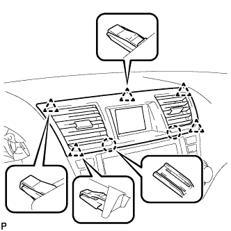
Engage the 2 claws and 5 clips, and install the center instrument panel register assembly.
-
-
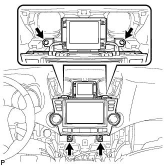
INSTALL COMBINATION METER ASSEMBLY
-
Connect the connector.
-
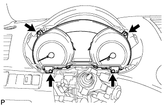
Install the combination meter assembly with the 4 screws <F>.
-
-
INSTALL INSTRUMENT CLUSTER FINISH PANEL ASSEMBLY
-
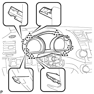
Engage the 4 claws and 4 clips, and install the instrument cluster finish panel assembly.
-
-
POSITION FRONT WHEELS STRAIGHT AHEAD
-
INSTALL TURN SIGNAL SWITCH ASSEMBLY WITH SPIRAL CABLE SUB-ASSEMBLY
-
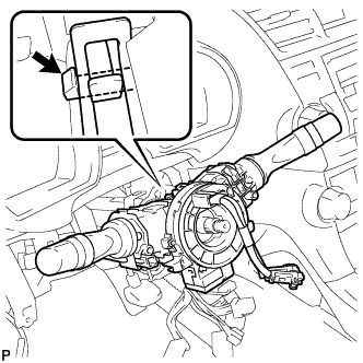
Using pliers, engage the claw. Install the turn signal switch assembly with spiral cable sub-assembly to the steering column assembly.
-
Connect the connectors to the turn signal switch assembly with spiral cable sub-assembly.
-
-
INSTALL STEERING COLUMN COVER
-
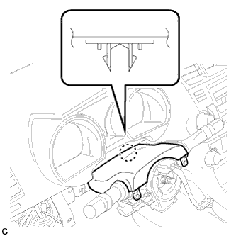
Engage the claw to install the upper steering column cover.
-
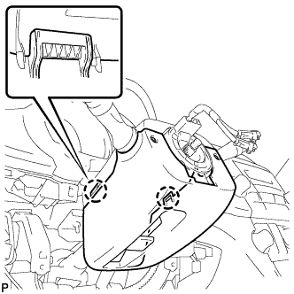
Engage the 2 claws to install the lower steering column cover.
-
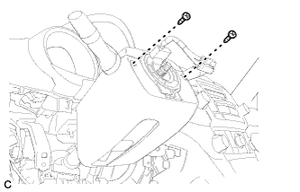
Install the 2 screws.
- Torque:
- 2.0 N*m { 20 kgf*cm, 18 in.*lbf }
-
-
ADJUST SPIRAL CABLE SUB-ASSEMBLY
-
Check that the ignition switch is off.
-
Check that the battery negative (-) cable is disconnected.
CAUTION:
Wait for at least 90 seconds after disconnecting the cable to prevent airbag deployment.
-
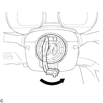
Rotate the spiral cable counterclockwise slowly by hand until it stops.
Note
Do not turn the spiral cable using the airbag wire harness.
-
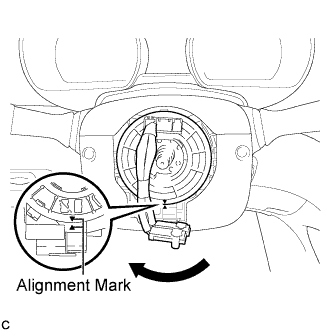
Rotate the spiral cable clockwise approximately 2.5 turns to align the marks.
Note
Do not turn the spiral cable using the airbag wire harness.
Tech Tips
The spiral cable will rotate approximately 2.5 turns to both the left and right from the center.
-
-
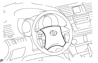
INSTALL STEERING WHEEL ASSEMBLY
-
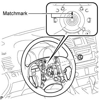
Align the matchmarks on the steering wheel assembly and steering main shaft.
-
Install the steering wheel assembly set nut.
- Torque:
- 50 N*m { 510 kgf*cm, 37 ft.*lbf }
-
Connect the connectors to the spiral cable sub-assembly.
-
-
INSPECT STEERING WHEEL CENTER POINT
-
INSTALL STEERING PAD
-
Check that the ignition switch is off.
-
Check that the battery negative (-) terminal is disconnected.
CAUTION:
Wait for at least 90 seconds after disconnecting the cable to prevent airbag deployment.
-
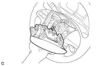
Support the steering pad with one hand as shown in the illustration.
-
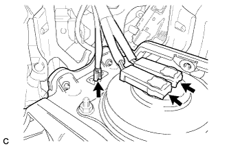
Connect the 2 airbag connectors to the steering pad.
Note
When handling the airbag connector, take care not to damage the airbag wire harness.
-
Connect the horn connector to the steering pad.
-
Confirm that the circumference groove of the "TORX" screw fits in the screw case, and place the steering pad onto the steering wheel assembly.
-
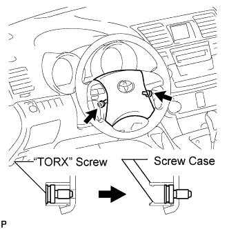
Using a "TORX" socket wrench (T30), tighten the 2 "TORX" screws.
- Torque:
- 8.8 N*m { 90 kgf*cm, 78 in.*lbf }
-
-
INSTALL LOWER NO. 2 STEERING WHEEL COVER
-
Install the lower No. 2 steering wheel cover with the claw.
-
-
INSTALL LOWER NO. 3 STEERING WHEEL COVER
-
Install the lower No. 3 steering wheel cover with the claw.
-
-
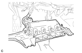
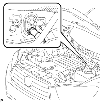
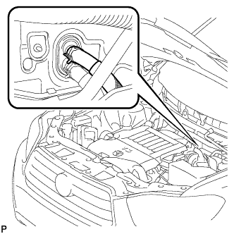
CONNECT COOLER REFRIGERANT LIQUID PIPE A
-
Remove the attached vinyl tape from the pipe.
-
Sufficiently apply compressor oil to a new O-ring and fitting surface of the cooler refrigerant liquid pipe A.
Compressor oil ND-OIL 8 or equivalent -
Install the O-ring on the cooler refrigerant liquid pipe A.
-
Install the cooler refrigerant liquid pipe A.
-
-
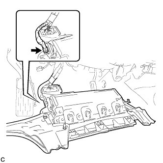
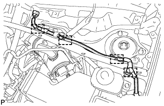
CONNECT NO. 1 COOLER REFRIGERANT SUCTION PIPE
-
Remove the attached vinyl tape from the pipe.
-
Sufficiently apply compressor oil to a new O-ring and the fitting surface of the No. 1 cooler refrigerant suction pipe.
Compressor oil ND-OIL 8 or equivalent -
Install the O-ring on the No. 1 cooler refrigerant suction pipe.
-
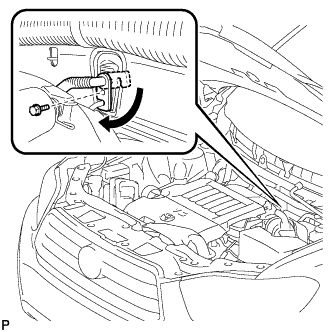
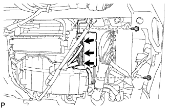
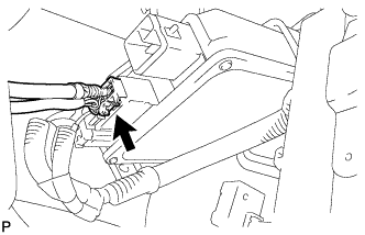
Move the hook connector in the direction indicated by the arrow in the illustration.
-
Insert the pipe joint into the fitting hole securely and tighten the bolt.
- Torque:
- 9.8 N*m { 100 kgf*cm, 87 in.*lbf }
-
-
CONNECT HEATER WATER HOSE INLET
-
Install the heater inlet water hose and attach the clip.
-
-
CONNECT HEATER WATER HOSE OUTLET
-
Install the heater outlet water hose and attach the clip.
-
-
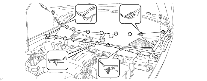
INSTALL COWL TOP OUTER PANEL SUB-ASSEMBLY
-
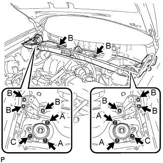
Install the outer cowl top panel sub-assembly with the 8 bolts and 6 nuts.
- Torque:
- Nut A
- 85 N*m { 866 kgf*cm, 63 ft.*lbf }
- Bolt B
- 8.8 N*m { 90 kgf*cm, 78 in.*lbf }
- Nut C
- 8.8 N*m { 90 kgf*cm, 78 in.*lbf }
-
Engage the 4 clamps.
-
-
INSTALL WINDSHIELD WIPER MOTOR AND LINK ASSEMBLY
-
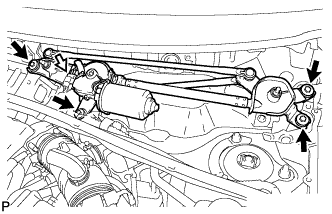
Install the windshield wiper motor and link assembly with the 4 bolts.
- Torque:
- 7.0 N*m { 71 kgf*cm, 62 in.*lbf }
-
Connect the connector.
-
-
INSTALL COWL TOP VENTILATOR LOUVER SUB-ASSEMBLY
-
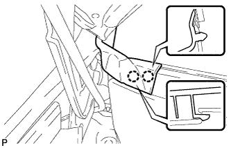
Engage the 20 claws.
-
Install the cowl top ventilator louver sub-assembly with the 2 clips.
-
Engage the 2 claws and connect the front fender to cowl side seal LH.
-
Engage the 2 claws and connect the front fender to cowl side seal RH.
-
-
INSTALL FRONT WIPER ARM AND BLADE ASSEMBLY RH
-
Operate the wiper and stop the windshield wiper motor at the automatic stop position.
-
When reinstalling:
-
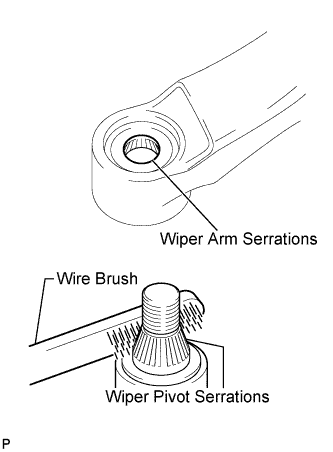
Clean the wiper arm serrations.
-
Clean the wiper pivot serrations with a wire brush.
-
-
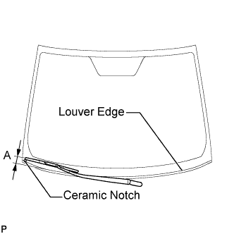
Install the front wiper arm and blade assembly RH with the nut to the position shown in the illustration.
- Torque:
- 24 N*m { 245 kgf*cm, 18 ft.*lbf }
Tech Tips
Hold the wiper arm by hand when tightening the nut.
Area Measurement A 25.6 mm (1.00 in.)
-
-
INSTALL FRONT WIPER ARM AND BLADE ASSEMBLY LH
-
Operate the wiper and stop the windshield wiper motor at the automatic stop position.
-
When reinstalling:
-
Clean the wiper arm serrations.
-
Clean the wiper pivot serrations with a wire brush.
-
-
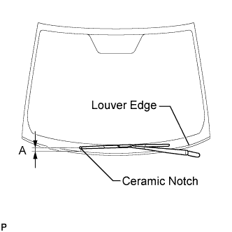
Install the front wiper arm and blade assembly LH with the nut to the position shown in the illustration.
- Torque:
- 24 N*m { 245 kgf*cm, 18 ft.*lbf }
Tech Tips
Hold the wiper arm by hand when tightening the nut.
Area Measurement A 31.9 mm (1.26 in.) -
Operate the front wipers while spraying washer fluid onto the windshield glass. Make sure that the front wipers function properly and the wipers do not come into contact with the vehicle body.
-
-
CONNECT CABLE TO NEGATIVE BATTERY TERMINAL
Note
When disconnecting the cable, some systems need to be initialized after the cable is reconnected Click here.
-
INSPECT STEERING PAD
-
With the steering pad installed on the vehicle, perform a visual check. If there are any defects as mentioned below, replace the steering pad with a new one:
-
Cuts, minute cracks or marked discoloration on the steering pad top surface or grooves.
-
-
Make sure that the horn sounds.
Tech Tips
If the horn does not sound, inspect the horn system Click here.
-
-
INSPECT SRS WARNING LIGHT
-
Inspect the SRS warning light Click here.
-
-
ADD ENGINE COOLANT
-
Tighten the radiator drain cock plug by hand.
-
Tighten the 2 cylinder block drain cock plugs.
- Torque:
- 13 N*m { 130 kgf*cm, 9 ft.*lbf, for cylinder block drain cock plugs }
-
Loosen the air drain cock plug from the water inlet housing.
-
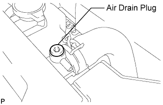
Loosen the air drain plug at the top of the radiator 3 or 4 turns.
-
Add TOYOTA Super Long Life Coolant (SLLC) to the radiator inlet opening until coolant overflows from the engine air drain cock hole. Then tighten the air drain cock plug to the water inlet housing.
- Torque:
- 13 N*m { 130 kgf*cm, 9 ft.*lbf, for air drain cock plug }
-
Continue to add TOYOTA Super Long Life Coolant (SLLC) to the radiator inlet opening until coolant overflows from the radiator air drain hole. Then close the air drain plug at the top of the radiator.
- Torque:
- 1.5 N*m { 15 kgf*cm, 13 in.*lbf, for air drain plug }
Tech Tips
If the coolant level at the radiator inlet opening drops after squeezing the No. 1 and No. 2 radiator hoses, add coolant.
-
Slowly fill the radiator with TOYOTA Super Long Life Coolant (SLLC).
Standard capacity w/o Engine oil cooler Condition Specified Condition w/ Rear Heater 11.0 liters (11.6 US qts, 9.7 Imp. qts) w/o Rear Heater 8.8 liters (9.3 US qts, 7.7 Imp. qts) w/ Engine oil cooler Condition Specified Condition w/ Rear Heater 11.7 liters (12.4 US qts, 10.3 Imp. qts) w/o Rear Heater 9.5 liters (10.1 US qts, 8.4 Imp. qts) Tech Tips
-
TOYOTA vehicles are filled with TOYOTA SLLC at the factory. In order to avoid damage to the engine cooling system and other technical problems, only use TOYOTA SLLC or similar high quality ethylene glycol based non-silicate, non-amine, non-nitrite, non-borate coolant with long-life hybrid organic acid technology (coolant with long-life hybrid organic acid technology consists of a combination of low phosphates and organic acids).
-
Contact your TOYOTA dealer for further details.
Note
Never use water as a substitute for engine coolant.
-
-
Slowly pour coolant into the radiator reservoir tank until it reaches the FULL line.
-
Squeeze the No. 1 and No. 2 radiator hoses several times by hand, and then check the level of the coolant.
If the coolant level is low, add coolant.
-
Bleed air from the cooling system.
-
Warm up the engine until the thermostat opens. While the thermostat is open, circulate the coolant for several minutes.
Tech Tips
The thermostat open timing can be confirmed by squeezing the inlet radiator hose by hand, and checking when the engine coolant starts to flow inside the hose.
-
Maintain the engine speed at 2500 to 3000 rpm.
-
Squeeze the inlet and outlet radiator hoses several times by hand to bleed air.
CAUTION:
When squeezing the radiator hoses:
-
Wear protective gloves.
-
Be careful as the radiator hoses are hot.
-
Keep your hands away from the radiator fan.
Note
-
Make sure that the radiator reservoir still has some coolant in it.
-
If the coolant temperature gauge indicates an excessive temperature, turn off the engine and let it cool.
-
If there is not enough coolant, the engine may overheat or be seriously damaged.
-
If the radiator reservoir does not have enough coolant, perform the following: 1) stop the engine, 2) wait until the coolant has cooled down, and 3) add coolant until the reservoir is filled to the FULL line.
-
-
-
Stop the engine and wait until the engine coolant cools down.
-
Add engine coolant to the FULL line on the radiator reservoir.
-
-
INSPECT FOR COOLANT LEAK
CAUTION:
Do not remove the radiator cap while the engine and radiator are still hot. Pressurized, hot engine coolant and steam may be released and cause serious burns.
Note
Before performing each inspection, turn the A/C switch off.
-
Fill the radiator with coolant and attach a radiator cap tester.
-
Warm up the engine.
-
Using the radiator cap tester, increase the pressure inside the radiator to 118 kPa (1.2 kgf/cm2, 17 psi), and check that the pressure does not drop.
If the pressure drops, check the hoses, radiator and water pump for leaks. If no external leaks are found, check the heater core, cylinder block and cylinder head.
-
-
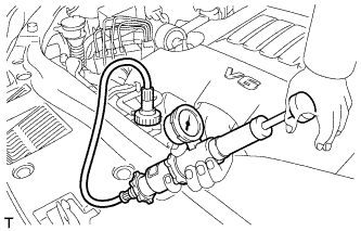
CHARGE WITH REFRIGERANT
-
Perform vacuum purging using a vacuum pump.
-
Charge with refrigerant HFC-134a (R134a).
Standard (w/o Rear Air Conditioning System) 550 to 650 g (19.4 to 22.9 oz.) Standard (w/ Rear Air Conditioning System) 720 to 820 g (25.4 to 28.9 oz.) - SST
- 09985-20010 ( 09985-02010, 09985-02050, 09985-02060, 09985-02070, 09985-02080, 09985-02090, 09985-02110, 09985-02130, 09985-02140, 09985-02150 )
Note
-
Do not turn the A/C on before charging with refrigerant. Doing so will cause the cooler compressor to work without refrigerant, resulting in overheating of the cooler compressor.
-
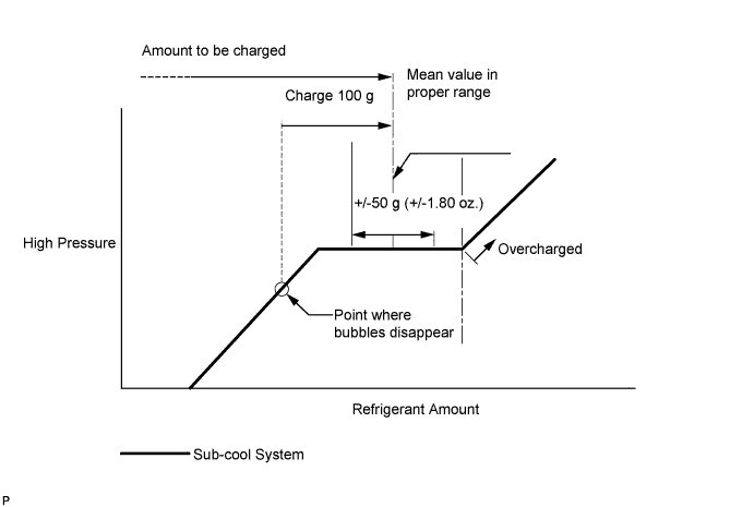
Approximately 100 g (3.53 oz.) of refrigerant may need to be charged after bubbles disappear. The refrigerant amount should be checked by quantity, not with the sight glass.
Tech Tips
Ensure that sufficient refrigerant is available to recharge the system when using a refrigerant recovery unit. Refrigerant recovery units are not always able to recover 100% of the refrigerant from an A/C system.
-
-
WARM UP ENGINE
-
Keep the A/C switch on for at least 2 minutes to warm up the compressor.
Note
Be sure to warm up the compressor when turning the A/C on after removing and installing the cooler refrigerant lines (including the compressor), to prevent damage to the compressor.
-
-
INSPECT FOR REFRIGERANT LEAK
-
After recharging with refrigerant gas, inspect for refrigerant leak using a halogen leak detector.
-
Carry out the test under the following conditions:
-
Make sure that the ignition switch is off.
-
Secure good ventilation (the gas leak detector may react to volatile gases which are not refrigerant, such as evaporated gasoline and exhaust gas).
-
Repeat the test 2 or 3 times.
-
Make sure that there is some refrigerant remaining in the refrigeration system.
When the compressor is off: approx. 392 to 588 kPa (4 to 6 kgf/cm2, 57 to 85 psi)
-
-
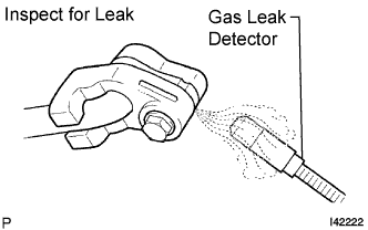
Using a gas leak detector, inspect for refrigerant leak from the refrigerant lines.
-
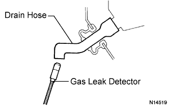
Bring the gas leak detector close to the drain hose with the detector's power off, and then turn the detector on.
Tech Tips
-
After the blower motor has stopped, let the cooling unit stand for more than 15 minutes.
-
Bring the gas leak detector sensor under the drain hose.
-
When bringing the gas leak detector close to the drain hose, make sure that the gas leak detector does not react to volatile gases.
If it is not possible to avoid interference from volatile gases, the vehicle should be lifted up to allow testing.
-
-
If a gas leak is not detected from the drain hose, remove the blower motor from the cooling unit. Insert the gas leak detector into the unit and perform the test.
-
Disconnect the pressure switch connector and leave it for approximately 20 minutes. Bring the gas leak detector close to the pressure switch and perform the test.
-
-
INITIALIZE SERVO MOTOR
-
Turn the ignition switch off.
-
Connect the intelligent tester to the DLC3.
-
Turn the ignition switch to on.
-
Press the A/C OFF switch.
-
Turn the intelligent tester on.
-
Enter the following menus: Body / Air Conditioner / Utility / Servomotor Initialization.
-
According to the intelligent tester display, select the "Next" switch.
-
According to the intelligent tester display, select the "Next" switch.
Tech Tips
During initialization, the AUTO indicator illuminates. When initialization is complete, the indicator turns off.
-
According to the intelligent tester display, select the exit to finish the initialization.
-