-
A large number of ECU controlled systems are used in this vehicle. In general, ECU controlled systems are considered to be very intricate, requiring a high level of technical knowledge to troubleshoot. However, most problem checking procedures only involve inspecting the ECU controlled system's circuits one by one. An adequate understanding of the system and a basic knowledge of electricity is enough to perform effective troubleshooting, accurate diagnoses and necessary repairs.
-
FOR USING INTELLIGENT TESTER
-
-
Before using the intelligent tester, read the operator's manual thoroughly.
-
If the tester cannot communicate with the ECU controlled systems when the tester is connected to the DLC3 with the ignition switch on (IG) and the tester turned on, there is a problem on the vehicle side or tester side.
-
-
If communication is normal when the tester is connected to another vehicle, inspect the diagnosis data link line (Bus (+) line) or ECU power circuit of the vehicle.
-
If communication is still not possible when the tester is connected to another vehicle, the problem is probably in the tester itself. Perform the Self Test procedures outlined in the tester operator's manual.
-
-
Click here
-
DESCRIPTION
-
Each system data and the Diagnostic Trouble Codes (DTCs) can be read from the Data Link Connector 3 (DLC3) of the vehicle. When the system seems to be malfunctioning, use the intelligent tester to check for malfunctions and perform repairs.
-
-
CHECK DLC3
-
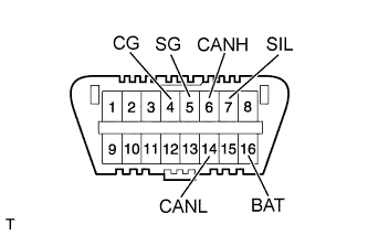
The vehicle's ECU uses the ISO 15765-4 communication protocol. The terminal arrangement of the DLC3 complies with ISO 15031-3 and matches the ISO 15765-4 format.
Symbols Terminal No. Names Reference Terminal Results Condition SIL 7 Bus "+" line 5 - Signal ground Pulse generation During transmission CG 4 Chassis ground Body ground 1 Ω or less Always SG 5 Signal ground Body ground 1 Ω or less Always BAT 16 Battery positive Body ground 11 to 14 V Always CANH 6 CAN "High" line 14 - CANL 54 to 69 Ω Ignition switch off* Battery positive 6 kΩ or higher Ignition switch off* 4 - CG 200 Ω or higher Ignition switch off* CANL 14 CAN "Low" line Battery positive 6 kΩ or higher Ignition switch off* 4 - CG 200 Ω or higher Ignition switch off* Note:*: Before measuring the resistance, leave the vehicle as is for at least 1 minute and do not operate the ignition switch, any other switches, or the doors.
If the result is not as specified, the DLC3 may have a malfunction. Repair or replace the harness and connector.
Tip:
-
If communication is normal when the tester is connected to another vehicle, inspect the DLC3 on the original vehicle.
-
If communication is still not possible when the tester is connected to another vehicle, the problem is probably in the tester itself. Consult the Service Department listed in the tester's instruction manual.
-
-