REPAIR INSTRUCTION INITIALIZATION
-
PROCEDURES NECESSARY WHEN BATTERY TERMINAL IS DISCONNECTED/RECONNECTED
Necessary Procedures Procedure Details Effects / Inoperative Functions When Necessary Procedures are not Performed Notes Reset back door close position Fully close the back door to turn off the courtesy switch. Power back door function If the back door is closed when disconnecting the cable from the battery terminal, it is not necessary to reset it. Note
-
After the engine switch is turned off, the navigation receiver assembly (HDD navigation system) records various types of memory and settings. As a result, after turning the engine switch off, make sure to wait at least 60 seconds before disconnecting the cable from the negative (-) battery terminal.
-
It may not be possible to release the steering lock or start the engine when the battery voltage is low. If this occurs, initialization of the steering lock system is required. Click here
-
-
PROCEDURES NECESSARY WHEN ECU OR OTHER PARTS ARE REPLACED
Replacement Part Necessary Procedures Effects / Inoperative Functions when Necessary Procedures are not Performed Notes
-
Automatic transaxle assembly
-
Engine assembly
Reset memory
-
Large shift shock
-
The deterioration of fuel efficiency
Using the intelligent tester. ECM Reset memory
-
Large shift shock
-
The deterioration of fuel efficiency
Using the intelligent tester. ECU communication ID registration Engine start See the Service Bulletin for the registration method.
-
Yaw rate and acceleration sensor
-
Brake actuator (Skid control ECU)
-
Clear zero point calibration data
-
Perform yaw rate and acceleration sensor zero point calibration
-
Slip indicator light comes on
-
VSC disabled or malfunctioning
Perform yaw rate and acceleration sensor zero point calibration with the ignition switch on (engine stopped). Steering lock actuator (Steering lock ECU) (*1) ECU code registration Engine start See the Service Bulletin for the registration method.
-
Certification ECU (*1)
-
Electrical key transmitter (*1)
Key ID registration
-
Wireless door lock control system
-
Smart Entry and Start System
-
Engine start
See the Service Bulletin for the registration method. ID code box (*1)
-
ECU code registration
-
ECU communication ID registration
-
Wireless door lock control system
-
Smart Entry and Start System
-
Engine start
See the Service Bulletin for the registration method. Transponder key ECU (*2)
-
Key code registration
-
ECU communication ID registration
-
Wireless door lock control system
-
Engine start
See the Service Bulletin for the registration method. Door control transmitter (*2) Key code registration Engine start See the Service Bulletin for the registration method. Refer to wireless door lock control system (w/o Smart Entry and Start System) "REGISTRATION" procedures Wireless door lock control system - Door control receiver (*2) Refer to wireless door lock control system (w/o Smart Entry and Start System) "REGISTRATION" procedures Wireless door lock control system -
-
Power window regulator motor (Driver door)
-
Front door window regulator (Driver door)
Perform power window reset (initialization of pulse sensor)
-
Automatic door glass open/close function
-
Jam protection function
-
Operation function after ignition switch off
-
Operation of each passenger window using power window switch at the driver door
Necessary when removed and installed. Steering angle sensor connector Correction of steering angle neutral point Parking guidance function - Back door lock motor Reset back door close position Power back door function -
-
Sliding roof drive gear (Sliding roof ECU)
-
Sliding roof housing
-
Sliding roof drive cable
Perform sliding roof drive gear reset
-
Automatic open/close function of roof glass
-
Jam protection function
-
Operation function after ignition switch off
Necessary when removed and installed (Not necessary when the sliding roof drive gear (sliding roof ECU) is removed and installed together with the sliding roof housing).
-
*1: w/ Smart Entry and Start System
-
*2: w/o Smart Entry and Start System
-
-
RESET MEMORY (Automatic Transaxle System)
Note
-
Perform the RESET MEMORY (AT initialization) when replacing the automatic transaxle assembly, engine assembly or ECM.
-
The RESET MEMORY can be performed only with Intelligent tester.
Tech Tips
The ECM memorizes the condition that the ECT controls the automatic transaxle assembly and engine assembly according to those characteristics. Therefore, when the automatic transaxle assembly, engine assembly, or ECM has been replaced, it is necessary to reset the memory so that the ECM can memorize the new information.
Reset procedure is as follows.
-
Turn the ignition switch off.
-
Connect the intelligent tester to the DLC3.
-
Turn the ignition switch on (IG) and push the intelligent tester main switch on.
-
Enter the following menu: Powertrain / Engine and ECT / Utility / Reset Memory. Then, press "Next".
-
Perform the reset memory procedure from the main menu.
CAUTION:
After performing the RESET MEMORY, be sure to perform the ROAD TEST Click here described earlier.
Tech Tips
The ECM is learned by performing the ROAD TEST.
-
-
OBTAIN ZERO POINT OF YAW RATE AND ACCELERATION SENSOR (When Using Intelligent Tester) (Vehicle Stability Control System)
Note
-
While obtaining the zero points, keep the vehicle stationary and do not vibrate, tilt, move, or shake it. (Do not start the engine.)
-
Be sure to perform this procedure on a level surface (with an inclination of less than 1 degree).
-
Clear the zero point calibration data.
-
Turn the ignition switch off.
-
Check that the steering wheel is in the straight-ahead position.
-
Check that the shift lever is in the P position.
-
Connect the intelligent tester to the DLC3.
-
Turn the ignition switch on (IG).
-
Turn the intelligent tester on.
-
Select the skid control ECU to clear the zero point calibration data using the intelligent tester. Enter the following menus: Chassis / ABS/VSC/TRC / Reset Memory.
-
Turn the ignition switch off.
Note
If the ignition switch is turned on (IG) for more than 15 seconds with the shift lever in the P position after the zero points of the yaw rate and acceleration sensor have been cleared, only the zero point of the yaw rate sensor will be stored. If the vehicle is driven under these conditions, the skid control ECU will store the zero point calibration for the acceleration sensor as not being completed. The skid control ECU will then also indicate this as a malfunction of the VSC system using the indicator lights.
-
-
Perform the zero point calibration of the yaw rate and acceleration sensor.
-
Turn the ignition switch off.
-
Check that the steering wheel is in the straight-ahead position.
-
Check that the shift lever is in the P position.
Note
DTCs C1210 (zero point calibration of yaw rate sensor undone) and C1336 (zero point calibration of acceleration sensor undone) will be recorded if the shift lever is not in the P position.
-
Connect the intelligent tester to the DLC3.
-
Turn the ignition switch on (IG).
-
Turn the intelligent tester on.
-
Switch the skid control ECU to Test Mode using the intelligent tester. Enter the following menus: Chassis / ABS/VSC/TRC / Test Mode.
-
After Test Mode has been entered, keep the vehicle stationary on a level surface for 2 seconds or more.
-
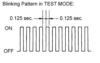
Check that the slip indicator light comes on for several seconds and then blinks in Test Mode.
Tech Tips
-
The TRC OFF indicator light remains on during Test Mode because TRC is prohibited.
-
If the slip indicator light does not blink, perform zero point calibration again.
-
The zero point calibration is performed only once after the system enters Test Mode.
-
Calibration cannot be performed again until the stored data is cleared.
-
-
Turn the ignition switch off and disconnect the intelligent tester.
-
-
-
OBTAIN ZERO POINT OF YAW RATE AND ACCELERATION SENSOR (When not Using Intelligent Tester) (Vehicle Stability Control System)
Note
-
While obtaining the zero points, keep the vehicle stationary and do not vibrate, tilt, move, or shake it. (Do not start the engine.)
-
Be sure to perform this procedure on a level surface (with an inclination of less than 1 degree).
-
Clear the zero point calibration data.
-
Turn the ignition switch off.
-
Check that the steering wheel is in the straight-ahead position.
-
Check that the shift lever is in the P position.
-
Turn the ignition switch on (IG).
-
The warning light and indicator light come on for 3 seconds to indicate that the initial check is completed.
-
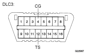
Using SST, connect and disconnect terminals TS and CG of the DLC3 4 times or more within 8 seconds.
- SST
- 09843-18040
-
Check that the slip indicator light comes on.
Note
If the ignition switch is turned on (IG) for more than 15 seconds with the shift lever in the P position after the zero points of the yaw rate and acceleration sensor have been cleared, only the zero point of the yaw rate sensor will be stored. If the vehicle is driven under these conditions, the skid control ECU will store the zero point calibration for the acceleration sensor as not being completed. The skid control ECU will then also indicate this as a malfunction of the VSC system using the indicator lights.
-
-
Perform the zero point calibration of the yaw rate and acceleration sensor.
-
Turn the ignition switch off.
-
Check that the steering wheel is in the straight-ahead position.
-
Check that the shift lever is in the P position.
Note
DTCs 36 (zero point calibration of yaw rate sensor undone) and 39 (zero point calibration of acceleration sensor undone) will be recorded if the shift lever is not in the P position.
-
Using SST, connect terminals TS and CG of the DLC3.
- SST
- 09843-18040
-
Turn the ignition switch on (IG).
-
After Test Mode has been entered, keep the vehicle stationary on a level surface for 2 seconds or more.
-
Check that the slip indicator light comes on for several seconds and then blinks in Test Mode.
Tech Tips
-
The TRC OFF indicator light remains on during Test Mode because TRC is prohibited.
-
If the slip indicator light does not blink, perform zero point calibration again.
-
The zero point calibration is performed only once after the system enters Test Mode.
-
Calibration cannot be performed again until the stored data is cleared.
-
-
Turn the ignition switch off and disconnect SST from the DLC3.
-
-
-
REGISTRATION OF RECOGNITION CODE (USING THE INTELLIGENT TESTER) (Wireless Door Lock Control System (w/o Smart Entry and Start System))
Tech Tips
For detailed procedures, refer to the prompts on the tester screen. The number of currently registered codes can be checked out on the first screen of the WIRELESS REGIST.
-
Turn the ignition switch to the ON position.
-
Enter the following menus: Body / MAIN BODY / Wireless Registration.
-
Press both LOCK and UNLOCK switches within 1 to 1.5 seconds.
-
Press either switch for more than 1 second within 3 seconds.
-
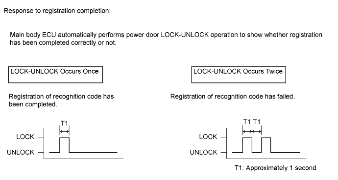
Check the response to the registration completion.
Tech Tips
-
If the LOCK-UNLOCK operation occurs twice, the registration of recognition code has failed. Perform the registration procedures again from the beginning.
-
If registering another transmitter, repeat the procedures after the tester operation. All 6 recognition codes can be registered consecutively.
-
-
Perform either of the following to complete the registration of recognition codes:
-
Use the intelligent tester to send completion command.
-
Disconnect the intelligent tester.
-
-
-
REGISTER RECOGNITION CODE (USING SWITCH OPERATION) (Wireless Door Lock Control System (w/o Smart Entry and Start System))
-
The following conditions should be met.
-
No key in the ignition key cylinder.
-
The driver side door is open (the other doors are closed).
-
The driver side door is unlocked.
-
-
Insert and remove the key into / from the ignition key cylinder twice (Insert → Remove → Insert → Remove) within 5 seconds.
Tech Tips
The procedure should end with the key removed.
-
Perform the following operations within 40 seconds.
-
Close and open the driver side door twice (Close → Open → Close → Open).
Tech Tips
The procedure should end with the door open.
-
Insert and remove the key into / from the ignition key cylinder (Insert → Remove).
Tech Tips
The procedure should end with the key removed.
-
Close and open the driver side door twice (Close → Open → Close → Open).
Tech Tips
The procedure should end with the door open.
-
Insert the key into the ignition key cylinder and close all doors.
-
-
Perform the following operations within 40 seconds.
-
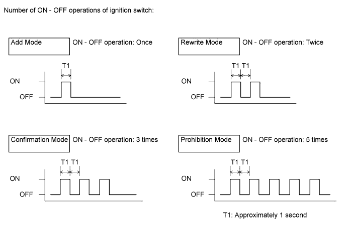
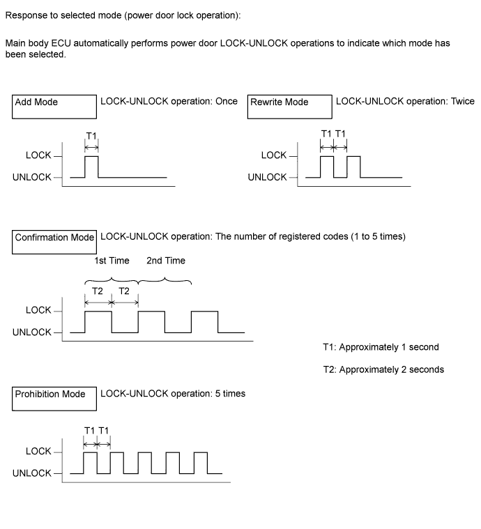
Turn the ignition switch from the ON to the OFF at approximately 1 second intervals, operate the ignition switch according to the number of times shown below.
Tech Tips
If the number of ignition switch ON - OFF operations is 0, 4, 6 or more, there will be no response (the power door lock and unlock operation) to show which mode has been selected.
-
Remove the key from the ignition key cylinder.
-
-
Check the response of the selected mode within 5 seconds.
Note
After the system has been set to the prohibition mode, enter the confirmation mode and check that the number of registered keys is 0.
Tech Tips
-
In the confirmation mode, LOCK-UNLOCK operation will occur once for each recognition code that has been registered. For example, if 2 recognition codes have been registered, LOCK-UNLOCK operation will occur twice.
-
In the confirmation mode, if no recognition codes have been registered, LOCK-UNLOCK operation will occur 5 times.
-
If confirmation mode or prohibition mode is selected, the operation ends after the response to the selected mode completes.
-
-
Within 40 seconds of completing the confirmation mode operation, press the LOCK and UNLOCK switches on the transmitter simultaneously.
-
After completing the above step, press a single switch (LOCK or UNLOCK) within 5 seconds.
-
After completing the above step, check the response to the registration completion within 3 seconds.
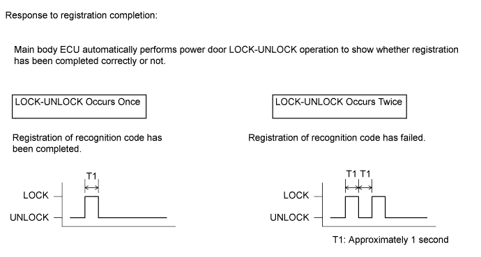
Tech Tips
-
If the LOCK-UNLOCK operation occurs twice, the registration of recognition code has failed. Perform registration procedures again from the beginning.
-
If registering another transmitter, repeat the procedures after the response to the selected mode confirmation. All 6 recognition codes can be registered consecutively.
-
-
Perform either of the following to complete the registration of recognition codes:
-
Open the door.
-
Insert the key into the ignition key cylinder.
-
-
-
INITIALIZE POWER WINDOW CONTROL SYSTEM (POWER WINDOW REGULATOR MOTOR ASSEMBLY (ON DRIVER SIDE)) (Power Window Control System)
Note
-
DTC B2313 will be set if the driver side power window regulator motor assembly is replaced with a new assembly. Clear the DTC after initializing the power window motor.
-
Initialization should be made when the vehicle is stationary.
-
Be sure to initialize the door glass position memory (pulse sensor) after replacing the driver side power window regulator motor assembly. Without the initialization, the driver door auto up-and-down function, jam protection function and key-off operation will not work.
-
Be sure not to tap or give any shock or force to the door glasses during the initialization procedure as the vehicle is learning the door glasses' sliding resistance during initialization.
-
After replacing the driver side power window regulator, door glass, or glass adhesive dams, be sure to initialize the door glass position memory (pulse sensor). Otherwise, the jam protection function may work when unnecessary.
If the initialization procedure cannot be completed normally, there may be a malfunction in the Local Interconnect Network (LIN) communication. Check the body multiplex (LIN, Local Interconnect Network) communication system.
-
Inspection procedure
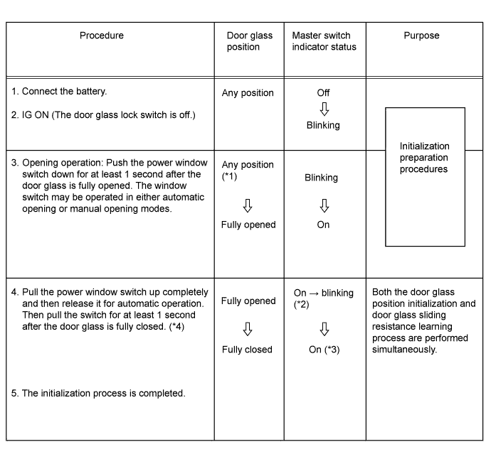
Tech Tips
-
*1: Even if the door glass has been fully opened before procedure No. 3, it is necessary to press the power window switch down for at least 1 second.
-
*2: As soon as the switch is pulled completely up (Automatic Closing), the master switch indicator starts to blink.
-
*3: If the master switch indicator does not come on after procedure No. 4, restart from procedure No. 3.
-
*4: Allow the automatic operation to continue without stopping until the door glass is fully closed.
Check the body multiplex (LIN, Local Interconnect Network) system Click here.
-
-
-
TO RETURN THE SYSTEM TO THE PRE-INITIALIZED CONDITION (RESET) (Power Window Control System)
Note
After replacing or reinstalling the driver side power window regulator, door glass, or door glass adhesive dams, be sure to initialize the door glass position memory (pulse sensor). Otherwise, the jam protection function may work when unnecessary.
-
Procedure
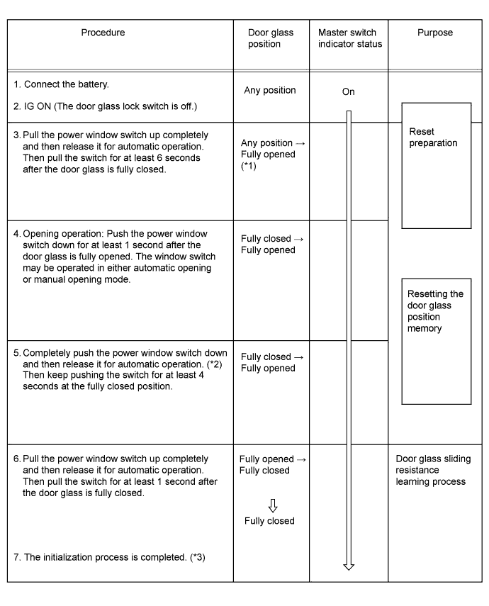
Tech Tips
-
*1: Even if the door glass has been fully closed before procedure No. 3, it is necessary to pull the power window switch up for at least 6 seconds while the door glass is fully closed.
-
*2: After completing procedure No. 4, return the door glass switch to its neutral position, then perform automatic opening operation.
-
*3: After completing the whole initialization process, make sure that the door glass fully closes with the automatic closing operation.
-
If the initialization procedure cannot be completed normally, there may be a malfunction in the Local Interconnect Network (LIN) communication. Check the body multiplex (LIN, Local Interconnect Network) communication system Click here.
-
-
-
RESET BACK DOOR CLOSE POSITION (Power Back Door System)
-
When disconnecting the cable from the battery terminal, fully close the back door to turn off the courtesy switch.
Tech Tips
If the back door is closed when disconnecting the cable from the battery terminal, it is not necessary to reset it.
-
-
INITIALIZE SLIDING ROOF DRIVE GEAR SUB-ASSEMBLY (Sliding Roof System)
Note
Be sure to initialize the sliding roof drive gear (pulse sensor) after adjusting the sliding roof glass position or removing and installing components. Without initialization, there may be a malfunction in the sliding roof auto operation, jam protection operation, or key-off operation.
If any of the following conditions occurs during initialization procedure, initialization will fail.
-
The ignition switch is turned off.
-
Communication is cut off.
-
Another switch is turned on during initialization.
-
Vehicle speed is 5 km/h (3 mph) or more.
-
The vehicle experiences a strong vibration during initialization, such as the slamming of a door.
-
Initialization
Tech Tips
According to the following chart, proceed to the appropriate initialization procedure.
Sliding Roof Condition Proceed to The sliding roof AUTO function does not operate. [A] The sliding roof AUTO function [B] Although the sliding roof AUTO function operates, the roof glass stops moving or starts moving in the opposite direction while tilting downward. [B] Although the sliding roof AUTO function operates, the roof glass stops moving or starts moving in the opposite direction while sliding closed. [C]
-
[A] The sliding roof AUTO function does not operate
-
Turn the ignition switch on (IG). *1
-
Fully close the sliding roof.
-
Press and hold the sliding roof switch (TILT UP side) until the following movement finishes: Tilt up → stationary state for at least 1 second → tilt down → slide open → slide close.
Note
Press and hold the sliding roof switch (TILT UP side) until step *2 is complete. If the switch is released before step *2 is complete, restart from step *1.
-
Confirm that the roof glass is stopped at the fully closed position and initialization is completed. *2
-
-
[B] Although the sliding roof AUTO function operates, the roof glass stops moving or starts moving in the opposite direction while tilting downward.
-
Turn the ignition switch on (IG). *1
-
Press and hold the sliding roof switch (TILT UP side) until the sliding roof stops.
-
After the sliding roof stops, release the switch.
-
Press and hold the sliding roof switch (TILT UP side) for more than 10 seconds until the following movement finishes: Tilt up → stationary state for at least 1 second → tilt down → slide open → slide close.
Note
Press and hold the sliding roof switch (TILT UP side) until step *2 is complete. If the switch is released before step *2 is complete, restart from step *1.
-
Confirm that the roof glass is stopped at the fully closed position and initialization is complete. *2
-
Confirm that the sliding roof can be normally operated with the AUTO function.
-
-
[C] Although the sliding roof AUTO function operates, the roof glass stops moving or starts moving in the opposite direction while sliding closed.
-
Turn the ignition switch on (IG). *1
-
Press and hold sliding roof switch (TILT UP side) until the following movement finishes: Slide close → roof glass stops moving or starts moving in the opposite direction → stationary for at least 10 seconds → slide close.
Note
Press and hold sliding roof switch (TILT UP side) until step *2 is complete. If the switch is released before step *2 is complete, restart from step *1.
-
After the sliding roof has stopped at the fully closed position, release the switch. *2
-
Follow the initialization procedure described in [A] (The sliding roof AUTO function does not function).
-
-
-