Click here
-
GENERAL
-
The air conditioning system has the following features:
-
Based on the signals from the ambient temperature sensor, this system calculates the outside temperature and indicates it in the multi-information display.
-
The Positive Temperature Coefficient (PTC) heater system contains a PTC heater that heats the air that has passed through the heater core to ensure the proper heater performance.
-
Turns the rear defogger and outside rear mirror heaters on for 15 minutes when the rear defogger switch is pressed. Turns them off if the switch is pressed while they are operating.
-
When a high load is applied to the EPS system, the EPS ECU will send a signal to the air conditioning amplifier. After receiving the signal, the air conditioning amplifier may turn off the rear defogger, front deicer, and seat heaters.
-
-
-
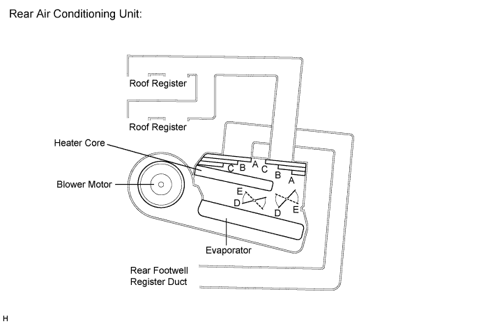
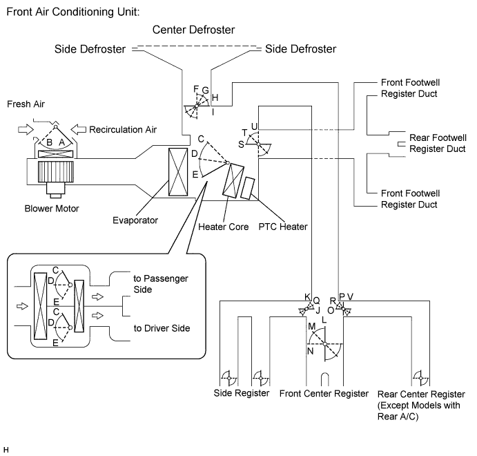
MODE POSITION AND DAMPER OPERATION
Control Damper Control Position Damper Position Operation Air Inlet Control Damper FRESH A Brings in fresh air RECIRC B Recirculates internal air Air Mix Control Damper
(Left/Right Independent Control)
Driver and Front Passenger Side MAX COOL to MAX HOT C, D, E Varies mixture ratio of fresh air and recirculation air in order to regulate temperature continuously from HOT to COOL Mode Control Film Damper Driver and Front Passenger Side 
FACE
I, J, L, O, U Air blows out of center registers and side registers. 
BI-LEVEL
I, M, Q, R, T Air mainly blows out of center registers, side registers, and footwell register ducts. 
FOOT
H, K, N, P, S Air mainly blows out of front and rear footwell register ducts.
In addition, air blows out slightly from front and side defrosters, and side registers.

FOOT/DEF
G, K, N, P, S Air mainly blows out of front and side defrosters to defrost windshield. Air also blows out from front and rear footwell register ducts, and side registers. 
DEF
F, K, N, U, V Air blows out of front and side defrosters and side registers to defrost windshield. Control Damper Control Position Damper Position Operation Air Mix Control Damper MAX COOL to HOT TEMP. SETING 18 to 32°C (65 to 90°F) D, E Varies mixture ration of fresh air and recirculating air in order to regulate temperature continuously from HOT to COOL Mode Control Film Damper FACE
A Air blows out of roof face ducts. BI-LEVEL
B Air blows out of roof face ducts and rear foot ducts. FOOT
C Air blows out of rear foot ducts. -
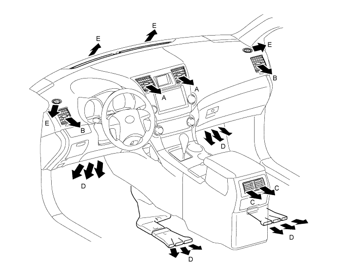
AIR OUTLET AND AIRFLOW VOLUME
The circle size (○) indicates the proportion of the flow volume.
Air Outlet Mode Air Outlet Position Symbol A B C D E Center Face Side Face Foot Footwell Defroster FACE 
X X X BI-LEVEL 

X FOOT X 
FOOT/DEF X DEF X X X Tip:The size of the circle ○ indicates the proportion of airflow volume.
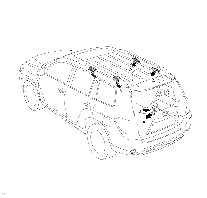
Air Outlet mode Air Outlet Position Symbol A B Side Face Rear Foot FACE X BI-LEVEL FOOT X -
A/C FLOW SENSOR
The A/C flow sensor, which is mounted on the compressor with pulley, is used to detect the amount of refrigerant flow. The A/C flow sensor converts the amount of refrigerant flow that is detected to a voltage value to send it to the A/C amplifier. The voltage value sent from the A/C flow sensor changes depending on the amount of refrigerant flow. As the amount of refrigerant flow becomes larger, the voltage becomes lower. As the amount of refrigerant flow becomes smaller, the voltage becomes higher. The A/C amplifier supplies 5 V to the A/C flow sensor and monitors change in the voltage value sent from the A/C flow sensor. The A/C amplifier then sends a signal to the ECM via CAN communication to allow the ECM to control the engine speed while the air conditioning is on.