AIR CONDITIONING SYSTEM (for Automatic Air Conditioning System) Back-up Power Source Circuit
DESCRIPTION
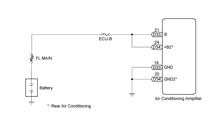
This is the back-up power source circuit for the air conditioning amplifier. Power is supplied even when the ignition switch is turned off and is used for functions such as the diagnostic trouble code memory.
WIRING DIAGRAM
INSPECTION PROCEDURE
PROCEDURE
-
INSPECT FUSE (ECU-B)
-
Remove the ECU-B fuse from the engine room No. 1 relay block.
-
Measure the resistance of the fuse.
Standard resistance Tester Connection Condition Specified Condition ECU-B fuse Always Below 1 Ω
NG 
REPLACE FUSE
OK 
-
-
CHECK HARNESS AND CONNECTOR (AIR CONDITIONING AMPLIFIER - BATTERY)
-
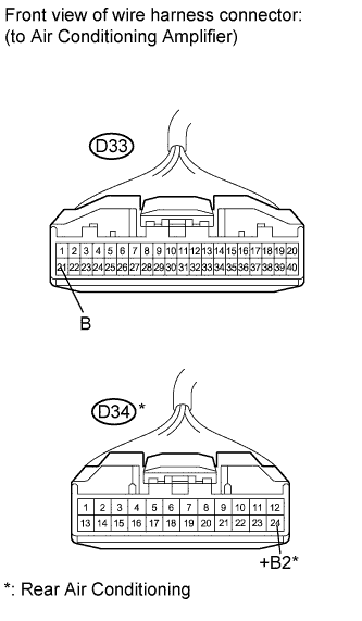
Disconnect the D33 and D34 amplifier connectors.
-
Measure the voltage according to the value(s) in the table below.
Standard voltage Tester Connection Condition Specified Condition D33-21 (B) - Body ground Always 11 to 14 V D34-24 (+B2)* - Body ground Always 11 to 14 V Tech Tips
*: w/ Rear Air Conditioning
NG
REPAIR OR REPLACE HARNESS OR CONNECTOR
OK
-
-
CHECK HARNESS AND CONNECTOR (AIR CONDITIONING AMPLIFIER - BODY GROUND)
-
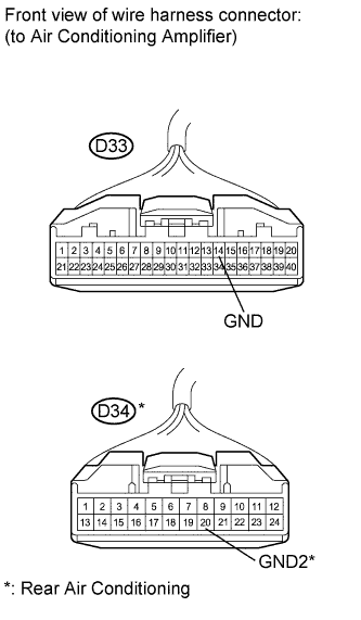
Disconnect the D33 and D34 amplifier connectors.
-
Measure the resistance according to the value(s) in the table below.
Standard resistance Tester Connection Condition Specified Condition D33-14 (GND) - Body ground Always Below 1 Ω D34-20 (GND2)* - Body ground Always Below 1 Ω Tech Tips
*: w/ Rear Air Conditioning
NG
REPAIR OR REPLACE HARNESS OR CONNECTOR
OK 
PROCEED TO NEXT CIRCUIT INSPECTION SHOWN IN PROBLEM SYMPTOMS TABLE Click here
-