AIR CONDITIONING SYSTEM (for Automatic Air Conditioning System) Steering Pad Switch Circuit
DESCRIPTION
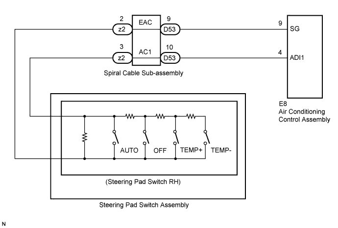
AUTO, OFF, TEMP UP (+), and TEMP DOWN (-) switches are located on the steering pad switch. The resistance of the steering pad switch changes in accordance with switch operation. The air conditioning control assembly outputs voltage to the steering pad switch and reads voltage changes due to the resistance changes that result from switch operation.
Tech Tips
If there is an open in the circuit, the air conditioning system cannot be operated by the steering pad switch assembly.
If there is a short in the circuit, the resulting condition is the same as if the switch were continuously depressed. Therefore, the air conditioning control assembly cannot be operated by the steering pad switch assembly, and the air conditioning control assembly will not be able to function correctly.
WIRING DIAGRAM
INSPECTION PROCEDURE
PROCEDURE
-
INSPECT AIR CONDITIONING CONTROL ASSEMBLY
-
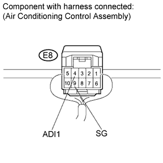
Remove the air conditioning control assembly Click here with the connectors still connected.
-
Measure the resistance according to the value(s) in the table below.
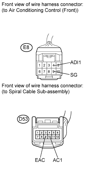
Standard resistance Tester Connection Condition Specified Condition E8-4 (ADI1) - E8-9 (SG) AUTO switch: ON Below 2.5 Ω E8-4 (ADI1) - E8-9 (SG) OFF switch: ON Approx. 329 Ω E8-4 (ADI1) - E8-9 (SG) TEMP+ switch: ON Approx. 1000 Ω E8-4 (ADI1) - E8-9 (SG) TEMP- switch: ON Approx. 3110 Ω
NG 
INSPECT STEERING PAD SWITCH ASSEMBLY Click here
OK 
PROCEED TO NEXT CIRCUIT INSPECTION SHOWN IN PROBLEM SYMPTOMS TABLE Click here
-
-
INSPECT STEERING PAD SWITCH ASSEMBLY
-
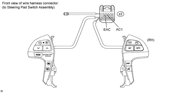
Remove the steering pad switch assembly.
-
Disconnect the connector from the steering pad switch assembly.
-
Measure the resistance according to the value(s) in the table below.
Standard resistance Tester Connection (Symbols) Condition Specified Condition z2-3 (AC1) - z2-2 (EAC) AUTO switch: ON Below 2.5 Ω z2-3 (AC1) - z2-2 (EAC) OFF switch: ON Approx. 329 Ω z2-3 (AC1) - z2-2 (EAC) TEMP+ switch: ON Approx. 1000 Ω z2-3 (AC1) - z2-2 (EAC) TEMP- switch: ON Approx. 3110 Ω
NG 
REPLACE STEERING PAD SWITCH ASSEMBLY Click here
OK 
-
-
INSPECT SPIRAL CABLE SUB-ASSEMBLY
-
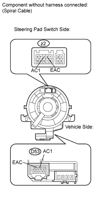
Disconnect the connector from the spiral cable sub-assembly.
-
Measure the resistance according to the value(s) in the table below.
Standard resistance Tester Connection Condition Specified Condition D53-10 (AC1) - z2-3 (AC1) Center Below 1 Ω D53-10 (AC1) - z2-3 (AC1) 2.5 rotations to the left Below 1 Ω D53-10 (AC1) - z2-3 (AC1) 2.5 rotations to the right Below 1 Ω D53-9 (EAC) - z2-2 (EAC) Center Below 1 Ω D53-9 (EAC) - z2-2 (EAC) 2.5 rotations to the left Below 1 Ω D53-9 (EAC) - z2-2 (EAC) 2.5 rotations to the right Below 1 Ω Note
The spiral cable is an important part of the SRS airbag system. Incorrect removal or installation of the spiral cable may prevent the airbag from deploying. Be sure to read the pages shown in the brackets below.
Tech Tips
The spiral cable makes a maximum of approximately 5 rotations.
NG
REPLACE SPIRAL CABLE SUB-ASSEMBLY Click here
OK
-
-
CHECK HARNESS AND CONNECTOR (A/C CONTROL ASSEMBLY - SPIRAL CABLE SUB-ASSEMBLY)
-
Disconnect the connector from the air conditioning control assembly.
-
Disconnect the connector from the spiral cable sub-assembly.
-
Measure the resistance according to the value(s) in the table below.
Standard resistance Tester Connection Condition Specified Condition E8-4 (ADI1) - D53-10 (AC1) Always Below 1 Ω E8-9 (SG) - D53-9 (EAC) Always Below 1 Ω E8-9 (ADI1) - D53-10 (AC1) Always 10 kΩ or higher E8-8 (SG) - D53-9 (EAC) Always 10 kΩ or higher
NG
REPAIR OR REPLACE HARNESS OR CONNECTOR
OK
REPLACE AIR CONDITIONING CONTROL ASSEMBLY Click here
-