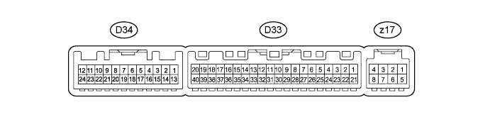
AIR CONDITIONING SYSTEM (for Manual Air Conditioning System) TERMINALS OF ECU
-
CHECK AIR CONDITIONING AMPLIFIER
-
Measure the voltage of the connectors.
Tech Tips
Check from the rear of the connector while it is connected to the air conditioning amplifier.
Tester Connection Wiring Color Terminal Description Condition Specified Condition D33-1 (IG+) - D33-14 (GND) GR - W-B Power source (IG) Ignition switch on (IG) 11 to 14 V D33-2 (SOL+) - D33-14 (GND) L - W-B A/C compressor operation signal Engine idling Pulse generation
(see waveform 1)
Blower switch LO A/C switch ON D33-3 (PTC1) - Body ground (*1) P - Body ground PTC NO. 1 heater relay operation signal Engine idling Below 1 V → 11 to 14 V Set temperature: MAX HOT Engine coolant temperature: Below 65°C (149°F) Ambient temperature: Below 10°C (50°F) Blower switch OFF → LO D33-4 (PTC3) - Body ground (*1) W - Body ground PTC NO. 3 heater relay operation signal Engine idling Below 1 V → 11 to 14 V Set temperature: MAX HOT Engine coolant temperature: Below 65°C (149°F) Ambient temperature: Below 10°C (50°F) Blower switch OFF → LO D33-5 (TAM) - D33-14 (GND) B - W-B Ambient temperature sensor signal Ignition switch on (IG) 1.8 to 2.2 V Ambient temperature: 25°C (77°F) D33-8 (LOCK) - D33-14 (GND) V - W-B Air compressor lock sensor signal Engine idling Pulse generation
(see waveform 5)
A/C switch ON Blower switch LO D33-9 (PRE) - D33-13 (SG-2) R - SB Air conditioning pressure sensor signal Refrigerant pressure: Normal 0.76 to 4.74 V D33-9 (PRE) - D33-13 (SG-2) R - SB Air conditioning pressure sensor signal Refrigerant pressure: Abnormal (less than 0.196 MPa [2.0 kgf/cm2, 28 psi])
0.5 to 4.83 V D33-9 (PRE) - D33-13 (SG-2) R - SB Air conditioning pressure sensor signal Refrigerant pressure: Abnormal (more than 3.14 MPa [32 kgf/cm2, 455 psi])
4.74 V or higher D33-10 (S5-3) - D33-14 (GND) O - W-B Power supply for pressure sensor Ignition switch on (IG) 4.5 to 5.5 V D33-11 (CANH) - D33-14 (GND) LG - W-B Hi-level CAN bus line Ignition switch on (IG) Pulse generation
(see waveform 3)
D33-12 (CANL) - D33-14 (GND) W - W-B Lo-level CAN bus line Ignition switch on (IG) Pulse generation
(see waveform 4)
D33-13 (SG-2) - Body ground SB - Body ground Ground for pressure sensor Always Below 1 V D33-14 (GND) - Body ground W-B - Body ground Ground for main power supply Always Below 1 V D33-20 (MGC) - D33-14 (GND) V - W-B A/C compressor magnetic clutch operation signal Engine idling Below 1 V Blower switch LO A/C switch ON D33-21 (B) - D33-14 (GND) B - W-B Power source (Back-up) Always 11 to 14 V D33-22 (PTC2) - Body ground (*1) G - Body ground PTC NO. 2 heater relay operation signal Engine idling Below 1 V → 11 to 14 V Set temperature: MAX HOT Engine coolant temperature: Below 65°C (149°F) Ambient temperature: Below 10°C (50°F) Blower switch OFF → LO D33-23 (BLW) - D33-14 (GND) R - W-B Blower motor control signal Ignition switch on (IG) Pulse generation
(see waveform 2)
Blower switch LO D33-25 (ALT) - Body ground (*1) SB - Body ground Generator signal Engine idling Pulse generation D33-27 (HLS) - Body ground (*1) V - Body ground Headlight signal Engine idling Below 1 V Headlight switch ON D33-37 (LIN1) - D33-14 (GND) R - W-B LIN communication signal Ignition switch on (IG) Pulse generation D33-38 (RDEF) - D33-14 (GND) W - W-B Rear defogger switch signal Ignition switch on (IG)
Rear defogger switch OFF
11 to 14 V D34-1 (RBUS) - D34-21 (RBUG) (*2) R - V BUS IC control signal (for Rear) Ignition switch on (IG) Pulse generation D34-4 (TEC) - D34-19 (SGND) (*2) B - GR Evaporator temperature sensor signal (for Rear) Ignition seitch on (IG) 1.4 to 1.8 V Evaporator temperature: 15°C (59°F) D34-13 (BLIN) - D34-20 (GND2) (*2) B - SB LIN communication signal (for Rear) Ignition switch on (IG) Pulse generation D34-19 (SGND) - Body ground (*2) GR - Body ground Ground for evaporator temperature sensor signal (for Rear) Always Below 1 V D34-20 (GND2) - Body ground (*2) SB - Body ground Ground for power supply Always Below 1 V D34-21 (RBUG) - Body ground (*2) V - Body ground Ground for BUS IC (for Rear) Always Below 1 V D34-22 (BLWH) - D34-20 (GND2) (*2) G - SB Blower motor control signal (for Rear) Ignition switch on (IG) Pulse generation Blower switch LO D34-23 (RBBU) - D34-21 (RBUG) (*2) Y - V Power supply for BUS IC (for Rear) Ignition switch on (IG) 11 to 14 V D34-24 (+B2) - D34-20 (GND2) (*2) LG - SB Power source (Back-up) (for Rear) Always 11 to 14 V z17-2 (BUS G) - Body ground - Ground for BUS IC Always Below 1 V z17-3 (BUS) - z17-2 (BUS G) - BUS IC control signal Ignition switch on (IG) Pulse generation z17-4 (B BUS) - z17-2 (BUS G) - Power supply for BUS IC Ignition switch on (IG) 11 to 14 V z17-5 (SG) - Body ground - Ground for evaporator temperature sensor Always Below 1 V z17-6 (TE) - z17-5 (SG) - Evaporator temperature sensor signal Ignition switch on (IG) 1.4 to 1.8 V Evaporator temperature: 15°C (59°F) -
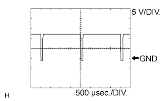
Using an oscilloscope, check waveform 1.
Compressor and pulley operation signal Item Content Tester Connection D33-2 (SOL+) - D33-14 (GND) Tool Setting 5 V/DIV., 500 μsec./DIV. Condition Engine idling, Blower switch LO, A/C switch ON -
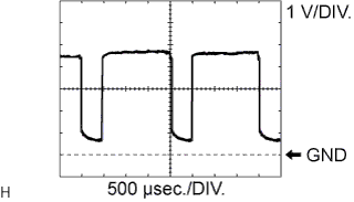
Using an oscilloscope, check waveform 2.
Blower motor control signal Item Content Tester Connection D33-23 (BLW) - D33-14 (GND) Tool Setting 1 V/DIV., 500 μsec./DIV. Condition Ignition switch on (IG), Blower switch LO Tech Tips
When the blower level is increased, the duty ratio changes accordingly.
-
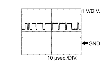
Using an oscilloscope, check waveform 3.
CAN communication signal Item Content Tester Connection D33-11 (CANH) - D33-14 (GND) Tool Setting 1 V/DIV., 10 μsec./DIV. Condition Ignition switch on (IG) Tech Tips
The waveform varies depending on the CAN communication signal.
-
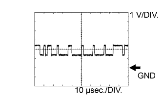
Using an oscilloscope, check waveform 4.
CAN communication signal Item Content Tester Connection D33-12 (CANL) - D33-14 (GND) Tool Setting 1 V/DIV., 10 μsec./DIV. Condition Ignition switch on (IG) Tech Tips
The waveform varies depending on the CAN communication signal.
-
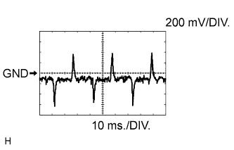
Using an oscilloscope, check waveform 5.
A/C compressor lock sensor signal Item Content Tester Connection D33-8 (LOCK) - D33-14 (GND) Tool Setting 200 mV/DIV., 10 ms./DIV. Condition Engine is running
Blower switch: LO
A/C switch: ON
Tech Tips
The waveform varies depending on the CAN communication signal.
*1: w/ PTC Heater
*2: w/ for Rear Air Conditioning
-
-
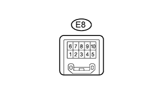
CHECK FRONT AIR CONDITIONING CONTROL
-
Measure the voltage of the connectors.
Tester Connection Wiring Color Terminal Description Condition Specified Condition E8-1 (IG+) - E8-6 (GND) V - GR Power source (IG) Ignition switch on (IG) 11 to 14 V E8-3 (LIN1) - E8-6 (GND) R - GR LIN communication signal LIN switch on (IG) Pulse generation E8-6 (GND) - Body ground GR - Body ground Ground for front air conditioning control Always Below 1 V
-
-
CHECK REAR AIR CONDITIONING CONTROL (for Rear Air Conditioning)

-
Measure the voltage of the connectors.
Tester Connection Wiring Color Terminal Description Condition Specified Condition R1-7 (IG+) - R1-12 (E) V - W-B Power source (IG) Ignition switch on (IG) 11 to 14 V R1-5 (MPX-) - R1-12 (E) B - W-B LIN communication signal LIN switch on (IG) Pulse generation R1-12 (E) - Body ground W-B - Body ground Ground for front air conditioning control Always Below 1 V
-